
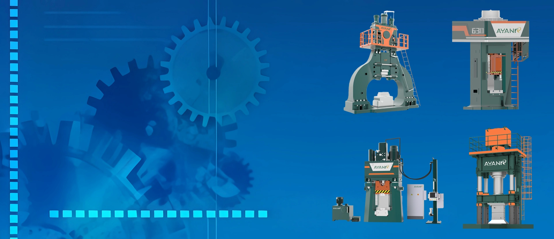
A hydraulic forging hammer is an industrial forging machine that uses a hydraulic drive and control system to generate and regulate high-energy hammer blows. Compared with traditional hammer systems, modern hydraulic forging hammers can provide more controllable blow energy, repeatable operation, and greater flexibility for open-die and closed-die forging applications.
Quick Answer
A hydraulic forging hammer uses hydraulic power to control the movement of the ram and deliver impact energy to a heated metal workpiece. During forging, the ram accelerates downward, the upper die strikes the billet, and the resulting impact causes the metal to plastically deform between the upper and lower dies.
Hydraulic forging hammers are commonly used for industrial open-die and closed-die forging where manufacturers require powerful impact forming, controllable blow energy, repeatable production, and compatibility with automated forging lines.
What Is a Hydraulic Forging Hammer?
A hydraulic forging hammer is a type of powered forging equipment in which a hydraulic system is used to drive, accelerate, return, or control the hammer ram. The moving ram carries the upper die or forging tool and transfers impact energy to the heated workpiece during each forging stroke.
The basic purpose is similar to other types of forging hammer: to convert machine energy into rapid impact energy that produces plastic deformation of metal. The major difference lies in how the ram movement and forging energy are generated and controlled.
Modern hydraulic hammer systems can be designed for both open-die and impression-die forging. Depending on the machine configuration, they can process components ranging from relatively simple shafts and rings to complex closed-die forgings used in automotive, machinery, railway, agricultural, and other industrial applications.
For a broader explanation of forging hammer classifications and applications, see What Is a Forging Hammer? Types, Working Principle & Applications.
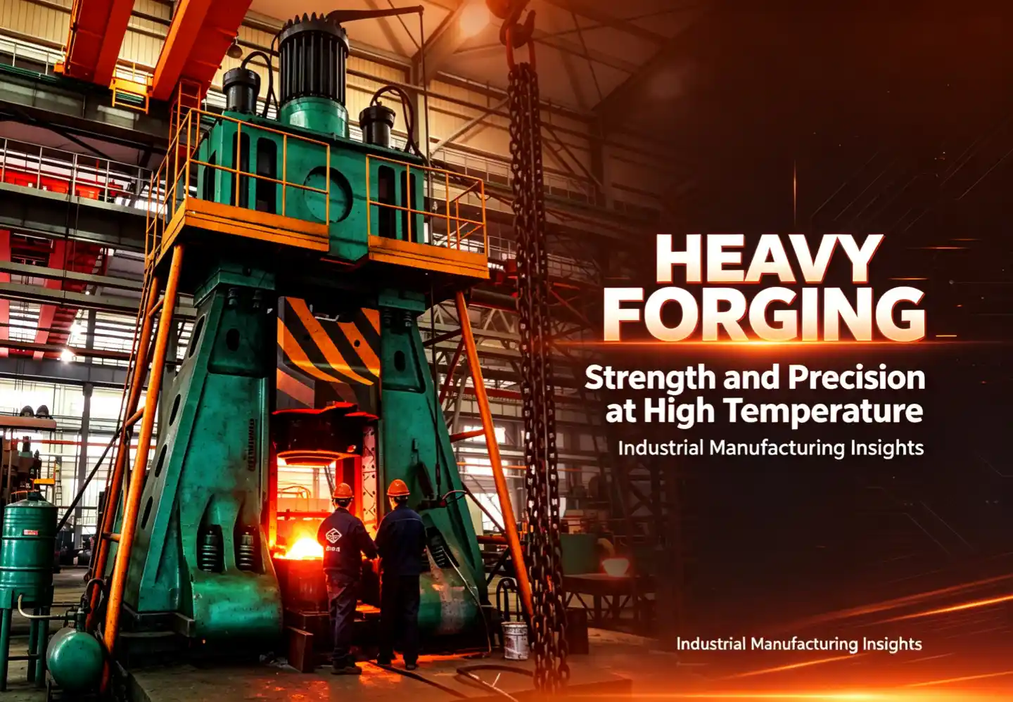
How Does a Hydraulic Forging Hammer Work?
The working principle of a hydraulic hammer for forging is based on converting hydraulic energy into controlled movement of the hammer ram and then into impact energy at the die. Although the exact hydraulic circuit varies according to machine design, the forging cycle generally follows the same basic sequence.
1. Hydraulic Power Is Generated
The hydraulic system provides the pressure and flow required to operate the hammer. Pumps, accumulators, valves, pipelines, and control components work together to supply energy to the machine's drive system.
Depending on the design, hydraulic accumulators may be used to store energy and make it available rapidly during the forging cycle.
2. The Ram Is Raised or Positioned
Before the forging blow, the ram and upper die are moved to the required position. The control system manages the hydraulic circuit so that the ram can be prepared for the next working stroke.
3. The Ram Accelerates Downward
During the working stroke, stored or supplied hydraulic energy contributes to the downward acceleration of the ram. The ram and upper die gain kinetic energy before contacting the workpiece.
4. Impact Energy Is Transferred to the Workpiece
When the upper die strikes the heated billet, the kinetic energy of the moving components is transferred into the workpiece. The metal undergoes plastic deformation and flows according to the die geometry, billet condition, and forging sequence.
5. Blow Energy Is Controlled
One important characteristic of a modern hydraulic forging system is the ability to control the working stroke according to the forging operation. Different forging stages may require different levels of impact energy.
For example, preliminary forming may use lighter blows, while final die filling may require a different energy setting. Appropriate control helps reduce unnecessary impact while improving process repeatability.
6. The Ram Returns for the Next Blow
After impact, the hydraulic system returns the ram to the required position. The cycle can then be repeated until the workpiece reaches the required shape.
Because hammer forging commonly uses multiple blows, the relationship between blow energy, billet temperature, die geometry, and forging sequence is important to the final process result.
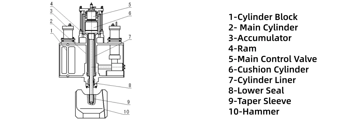
Main Components of a Hydraulic Forging Hammer
A complete hydraulic forging hammer machine consists of more than a hydraulic cylinder and ram. Its structural, hydraulic, control, and tooling systems must work together under repeated dynamic loads.
Machine Frame
The frame supports the working components of the hammer and must maintain structural stability under repeated forging impacts. Frame rigidity and construction are important considerations for machine durability and operating stability.
Ram and Hammer Head
The ram is the primary moving component of the hammer. It carries the upper die or forging tool and transfers kinetic energy into the workpiece during impact.
Ram mass, working velocity, stroke, and the drive system all influence the energy characteristics of the forging blow.
Hydraulic Drive System
The hydraulic drive system generates and controls the energy required for ram movement. It may include hydraulic pumps, valves, accumulators, cylinders, pipelines, filters, and other hydraulic components according to the machine design.
Hydraulic Accumulator
In systems equipped with accumulators, hydraulic energy can be stored and released when required. This helps provide the rapid energy delivery needed for repeated forging cycles.
Upper and Lower Dies
Closed-die hydraulic forging hammers use shaped upper and lower dies to form the workpiece. The die impressions determine material flow through the different forging stages and ultimately define the geometry of the forged component.
Anvil and Die Support
The lower die and its supporting structure receive the impact load generated during each blow. Their design must provide adequate support and maintain die positioning throughout production.
Control System
Modern hydraulic forging equipment may use electronic or programmable controls to manage operating parameters, working cycles, safety interlocks, and communication with auxiliary equipment.
When integrated into an automatic forging line, the control system can coordinate the hammer with induction heating, billet feeding, manipulators, robots, trimming equipment, and downstream handling.
Types of Hydraulic Forging Hammers
Hydraulic forging hammers can be classified in several ways, including their forging process, die arrangement, structural design, and intended application. For equipment buyers, one of the most useful distinctions is between open-die and closed-die hydraulic hammer systems.
Hydraulic Open-Die Forging Hammer
An open-die hydraulic forging hammer forms metal between relatively simple dies or forging tools rather than completely enclosing the workpiece inside a shaped die cavity.
The workpiece can be repositioned between blows so that different areas are progressively forged. Typical operations may include drawing, upsetting, flattening, elongating, and shaping.
Open-die forging hammers are commonly associated with lower-volume production, flexible forging operations, and components whose geometry does not require a fully enclosed impression die.
Hydraulic Die Forging Hammer
A hydraulic die forging hammer uses shaped upper and lower dies containing impressions of the required forged component. The heated billet is progressively formed through one or more die impressions until the final geometry is achieved.
This type of equipment is particularly relevant to repeat production of industrial components where dimensional consistency, die filling, productivity, and controlled forging energy are important.
Hydraulic die forging hammers can be used for components such as gears, connecting parts, shafts, flanges, levers, machinery parts, and other closed-die forgings.
Hydraulic Forging Hammer vs Pneumatic Forging Hammer
Hydraulic and pneumatic forging hammers both use powered systems to control ram movement, but the method used to generate and regulate that movement is different.
| Factor | Hydraulic Forging Hammer | Pneumatic Forging Hammer |
|---|---|---|
| Primary Power Medium | Hydraulic fluid | Compressed air |
| Ram Control | Hydraulic drive and valve control | Pneumatic pressure and air control |
| Typical Industrial Use | Open-die and closed-die production | General forging and open-die applications depending on design |
| Automation | Can be integrated into automated forging systems | Depends on machine configuration and control system |
| Selection Basis | Forging size, required energy, material, process, production rate, tooling, investment, and automation requirements | |
The choice should therefore not be based simply on whether hydraulic or pneumatic technology is considered more advanced. The correct machine depends on the actual forging process and production requirements.
Hydraulic Forging Hammer vs Mechanical Forging Hammer
Mechanical forging hammers use mechanical transmission systems to convert motor power into repeated hammer motion, while hydraulic forging hammers rely on hydraulic power and control systems.
This difference affects machine construction, energy control, maintenance requirements, operating characteristics, and the way each system is integrated into a production process.
When replacing an older mechanical hammer, manufacturers should evaluate the complete forging process rather than selecting a hydraulic machine solely according to the nominal specification of the existing equipment.
Forging drawings, material grade, billet size, required blow energy, die arrangement, production volume, and automation targets should all be reviewed before determining an appropriate replacement.
Advantages of Hydraulic Forging Hammers
The advantages of a hydraulic hammer depend on the specific machine design and application, but modern industrial systems can provide several important process benefits.
Controllable Forging Energy
Hydraulic control allows the machine to regulate the working cycle and adapt the forging blow to different forming stages. This can be useful when preliminary forming and final die filling require different impact conditions.
Repeatable Production
Controlled operating parameters can improve consistency between forging cycles, particularly when billet temperature, die condition, feeding, and other process variables are also properly controlled.
Suitable for Industrial Automation
Hydraulic forging equipment can be integrated with automated billet heating, feeding, robotic transfer, trimming, conveying, and production monitoring systems.
Flexible Forging Process
Multiple controlled blows allow the forging sequence to be adapted to different stages of material deformation rather than relying on a single impact.
Applicable to Different Forging Operations
Depending on machine and tooling design, hydraulic forging hammers can support both open-die and closed-die applications across a range of industrial components.
Limitations and Considerations of Hydraulic Forging Hammers
Although a hydraulic forging hammer can provide controllable impact energy and flexible production, it is not automatically the best solution for every forging process. Equipment selection should also consider the characteristics and operating requirements of impact-based forging.
Dynamic Impact Loads
Hammer forging generates repeated dynamic loads. Machine foundations, surrounding equipment, workshop structures, and vibration control should therefore be considered during installation planning.
Hydraulic System Maintenance
Hydraulic oil condition, filtration, seals, valves, pipelines, accumulators, and other hydraulic components require regular inspection and preventive maintenance. Hydraulic contamination or component wear can affect operating stability and machine reliability.
Process Variables Still Matter
A modern control system cannot compensate for every process problem. Billet temperature, die condition, lubrication, billet positioning, material variation, and forging sequence can all influence the final result.
Not Every Part Requires Hammer Forging
Some forged components may be better suited to an electric screw press, mechanical press, hydraulic press, or another forming process. The decision should be based on the complete manufacturing process rather than machine type alone.
Applications of Hydraulic Forging Hammers
A hydraulic hammer for forging can be used for a wide range of industrial components. The actual application depends on hammer capacity, blow energy, die dimensions, workpiece material, forging temperature, and production requirements.
Automotive Forgings
Closed-die hydraulic forging hammers can be used in the production of automotive and commercial vehicle components where repeatable die filling and high production output are required.
Typical applications may include transmission components, connecting parts, levers, hubs, shafts, and other forged components depending on the production process.
Gears and Shafts
Gear blanks, stepped shafts, and similar components often require controlled material flow and multiple forming stages. Hammer forging allows the workpiece to be progressively shaped through repeated blows.
Flanges and Industrial Fittings
Hydraulic forging equipment can also be applied to flanges, fittings, and other components that require upsetting, preforming, and final die forming operations.
Agricultural and Construction Machinery Parts
Components for agricultural, mining, and construction machinery often require high strength and durability. Appropriate hammer forging processes can be used to manufacture a variety of these load-bearing components.
Railway and General Machinery Components
Depending on the component geometry and required production process, hydraulic forging hammers can also be used for railway parts, industrial machinery components, hand tools, and other steel forgings.
Hydraulic Forging Hammer vs Forging Press
One of the most common equipment-selection questions is whether a component should be produced on a forging hammer or a forging press. The fundamental difference is how forming energy or force is delivered to the workpiece.
A hydraulic forging hammer delivers rapid impact blows. A forging press generally applies force over a longer portion of the working stroke. This difference affects deformation behavior, forging sequence, equipment requirements, and process design.
| Factor | Hydraulic Forging Hammer | Forging Press |
|---|---|---|
| Forming Method | High-speed impact | Progressive pressure |
| Typical Forming Sequence | Multiple controlled blows | One or more controlled press strokes |
| Energy / Force Control | Controlled through hammer operating parameters | Controlled through press force, energy, stroke, or position depending on design |
| Dynamic Load | Higher impact loading | Generally lower impact loading |
| Foundation Requirements | Impact and vibration must be considered | Depends on press structure, capacity, and process |
| Process Selection | Should be determined from the forged part, material, die process, required forming energy, production volume, and automation requirements. | |
There is therefore no universal rule that a hydraulic forging hammer or forging press is always the better option. The correct choice depends on the specific forged component and production conditions.
How to Select a Hydraulic Forging Hammer
Selecting a hydraulic forging hammer machine should begin with the forged component and process requirements. Choosing equipment only according to part weight or an existing machine's nominal size can lead to an incorrect selection.
1. Forged Part Material
Carbon steel, alloy steel, stainless steel, and other forgeable materials have different deformation characteristics and forging temperature ranges. Material grade therefore affects the energy and process required to form the component.
2. Billet Size and Weight
Billet dimensions and weight provide important information about material volume, but they should not be used as the only basis for hammer selection.
3. Forged Part Geometry
A simple component and a complex closed-die forging of similar weight may require very different forming conditions. Projected area, section changes, ribs, bosses, cavities, and material-flow distance can influence the required forging process.
4. Required Blow Energy
Blow energy is one of the most important parameters in hammer selection. It describes the energy available during the forging impact and should be matched to the deformation required at each stage of the process.
This is why two forging hammers that appear similar in nominal size should not automatically be considered equivalent. Their actual energy characteristics, ram design, control system, and application range may differ.
5. Die Dimensions and Forging Stages
The available die space must accommodate the required tooling. Buyers should also determine whether the component requires preforming, blocking, finishing, trimming, or other operations.
6. Production Capacity
Annual output and required hourly production influence hammer configuration, heating capacity, material handling, die arrangement, and the level of automation required.
7. Automation Requirements
For high-volume production, equipment selection should consider the complete forging line rather than the hammer alone. Billet heating, feeding, robotic transfer, trimming, cooling, and downstream handling can determine the actual production cycle.
8. Existing Factory Conditions
Foundation conditions, available floor space, lifting capacity, electrical supply, cooling, hydraulic auxiliary systems, and workshop layout should be evaluated before installation.
If you are comparing different hammer capacities, see How to Choose a Forging Hammer for a broader overview of forging hammer selection.
Why Blow Energy Matters More Than Hammer Size Alone
Buyers sometimes compare forging hammers primarily by machine size or another headline specification. In practice, the ability to produce a particular forging depends on how much useful energy can be delivered to the workpiece and how that energy is controlled during the forging sequence.
The required blow energy is influenced by several variables:
- Material grade and deformation resistance
- Billet temperature
- Workpiece dimensions and weight
- Projected forging area
- Part complexity
- Reduction required during each forging stage
- Die geometry
- Number of forging blows
For this reason, a manufacturer should evaluate the actual forged component before recommending a specific hydraulic forging hammer. A part drawing and process information provide much more useful selection data than a request based only on nominal hammer size.
Hydraulic Forging Hammer Production Line
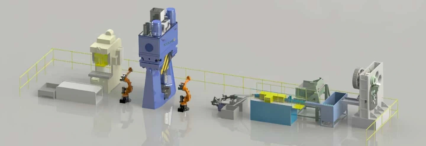
A modern hydraulic forging hammer does not need to operate as an isolated machine. For repeat production, it can become the central forming unit of an integrated forging production line.
A typical line may include:
- Raw material preparation and billet cutting
- Induction heating or furnace heating
- Billet temperature monitoring
- Automatic billet feeding
- Preforming equipment where required
- Hydraulic forging hammer
- Robot or manipulator transfer
- Trimming equipment
- Cooling and conveying
- Process monitoring and production control
The correct configuration depends on the forging sequence. For example, simply adding a robot does not automatically create an efficient automatic forging line. Heating cycle, transfer distance, hammer cycle, die layout, trimming, and downstream handling must be coordinated.
Maintenance of a Hydraulic Forging Hammer
Preventive maintenance is particularly important for forging equipment because the machine operates under repeated dynamic loads. A maintenance program should be based on the manufacturer's requirements, operating hours, production conditions, and actual machine configuration.
Hydraulic Oil and Filtration
Hydraulic fluid condition should be monitored and filters replaced according to the maintenance schedule. Contamination can accelerate wear in valves, pumps, cylinders, and other precision hydraulic components.
Seals and Hydraulic Connections
Cylinders, pipelines, joints, and seals should be inspected for leakage, damage, and abnormal wear. Changes in hydraulic pressure or response may indicate a developing system problem.
Accumulator System
Where accumulators are used, their operating condition and associated safety components should be checked according to the equipment manufacturer's maintenance procedures.
Ram and Guide System
Ram alignment, guides, clearances, lubrication, and wear should be inspected regularly. Abnormal movement can affect both machine operation and die alignment.
Forging Dies
Dies should be checked for cracking, excessive wear, deformation, and other damage. Die condition directly affects forged-part quality and production stability.
Fasteners and Structural Components
Repeated impact can affect fasteners and structural connections. Inspection should therefore include critical bolts, mounting points, frame components, and other load-bearing structures specified by the manufacturer.
What Information Should You Provide to a Hydraulic Forging Hammer Manufacturer?
If you are requesting a quotation or technical proposal, providing complete forging information helps the equipment manufacturer evaluate a more appropriate machine and production configuration.
| Required Information | Purpose |
|---|---|
| Forged part drawing | Evaluate geometry, dimensions and forming difficulty |
| Material grade | Evaluate deformation characteristics and forging temperature |
| Billet dimensions | Determine initial material condition |
| Billet and final part weight | Support preliminary process and equipment evaluation |
| Current forging process | Understand existing production conditions and problems |
| Required annual output | Evaluate productivity and automation requirements |
| Existing equipment | Useful when replacing or upgrading an existing forging line |
| Factory layout | Support installation and production-line planning |
| Automation requirements | Determine feeding, transfer and auxiliary equipment configuration |
Providing these details allows AYANK's engineering team to evaluate the forging process rather than recommending equipment based on a single nominal parameter.
Hydraulic Forging Hammer FAQ
What is a hydraulic forging hammer?
A hydraulic forging hammer is an industrial forging machine that uses a hydraulic system to control ram movement and deliver impact energy to a heated metal workpiece. It can be used for open-die and closed-die forging depending on the machine and tooling configuration.
How does a hydraulic forging hammer work?
Hydraulic power controls and accelerates the hammer ram. The upper die attached to the ram strikes the heated billet, transferring kinetic energy into the metal. Repeated controlled blows progressively deform the workpiece into the required shape.
What is the difference between a hydraulic forging hammer and a pneumatic forging hammer?
A hydraulic forging hammer uses hydraulic fluid and hydraulic control components to manage ram movement, while a pneumatic forging hammer primarily uses compressed air. Their construction, control characteristics, maintenance requirements, and suitable applications can therefore differ.
What is a hydraulic die forging hammer used for?
A hydraulic die forging hammer is used for impression-die or closed-die forging. Heated billets are formed between shaped upper and lower dies to produce repeatable industrial components such as gears, shafts, flanges, automotive parts, and machinery forgings.
How do I choose the correct hydraulic forging hammer?
Selection should consider material grade, billet dimensions, forged-part geometry, required blow energy, die dimensions, forging stages, production volume, factory conditions, and automation requirements. Part weight alone is not sufficient for accurate machine selection.
Can a hydraulic forging hammer be used in an automatic forging line?
Yes. A hydraulic forging hammer can be integrated with induction heating, automatic billet feeding, robots or manipulators, trimming equipment, conveyors, cooling systems, and production monitoring equipment.
Is a hydraulic forging hammer better than a forging press?
The two machines use different forming methods. A forging hammer delivers rapid impact blows, while a forging press generally applies force over a longer working stroke. The appropriate process depends on the component geometry, material, dies, required forming energy, production volume, and automation requirements.
Conclusion
A hydraulic forging hammer combines impact-based metal forming with hydraulic drive and control technology. It can be configured for open-die or closed-die forging and integrated into automated production systems for a wide range of industrial components.
However, selecting the correct hydraulic hammer for forging requires more than comparing nominal machine specifications. Material, billet size, forged-part geometry, blow energy, die design, production capacity, factory conditions, and automation requirements should be evaluated together.
AYANK provides forging hammer equipment and forging production solutions for industrial metal-forming applications. When requesting equipment selection, send your part drawing, material grade, billet dimensions, part weight, required output, and current forging process so that the appropriate machine configuration can be evaluated.