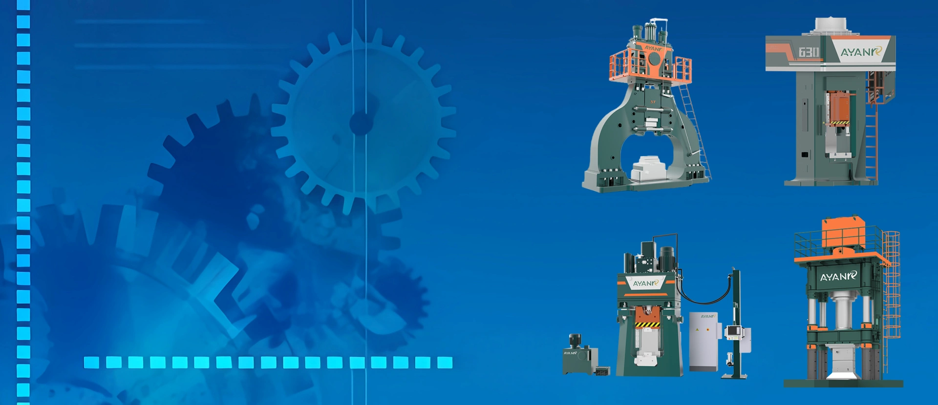
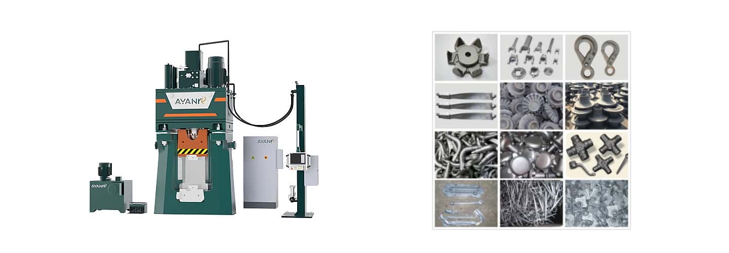
 I.Introduction to AYANK FORGING CNC Fully Hydraulic Die Forging Hammer Equipment
The C92KA series CNC Forging Hammer is a forging equipment with digitally controlled striking energy, featuring an energy deviation within ±3%, which places it at an internationally advanced level. It offers the following advantages:
1、Striking energy and forging sequences can be numerically controlled.
2、High striking frequency, fast return speed, and extended die lifespan.
3、Upper and lower die misalignment ≤0.2mm, ensuring forging precision and high material utilization.
4、Equipped with vibration-damping devices manufactured with German technology, reducing vibration by 80%.
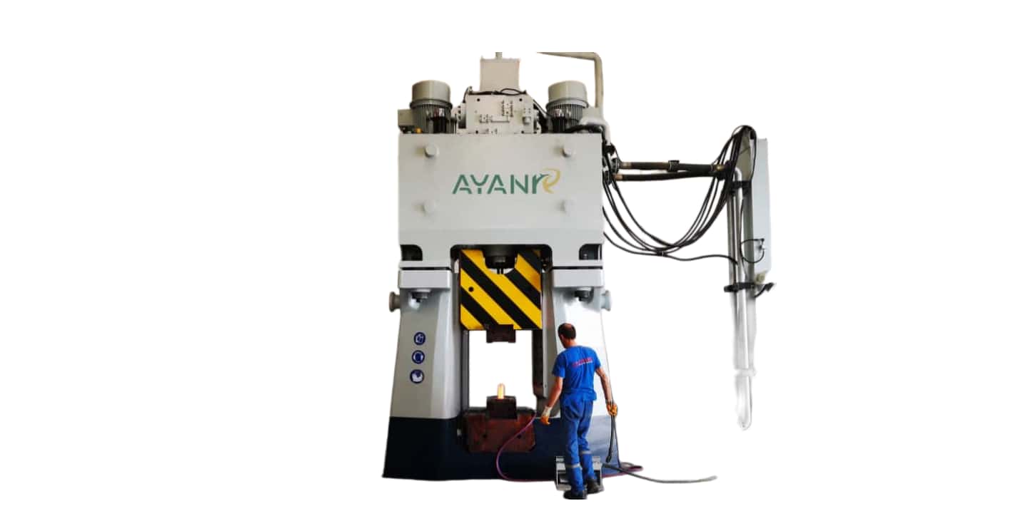
The hammer’s working cylinder is hydraulically driven in both the upper and lower chambers. The lower chamber is permanently connected to an accumulator with pressurized oil, while the control system only regulates the upper chamber. The hammer is lifted by directing the control valve (striking valve) to return oil to the tank. For striking, the control valve connects the upper and lower chambers, enabling rapid differential motion striking through the area difference between the rod and non-rod chambers. For hammers with energy levels above 80KJ, the striking valve is controlled by a two-stage pilot valve system: the first-stage pilot valve controls the second-stage pilot valve, which in turn controls the striking valve. The digital system precisely regulates striking energy by adjusting the closing time of the first-stage pilot valve.
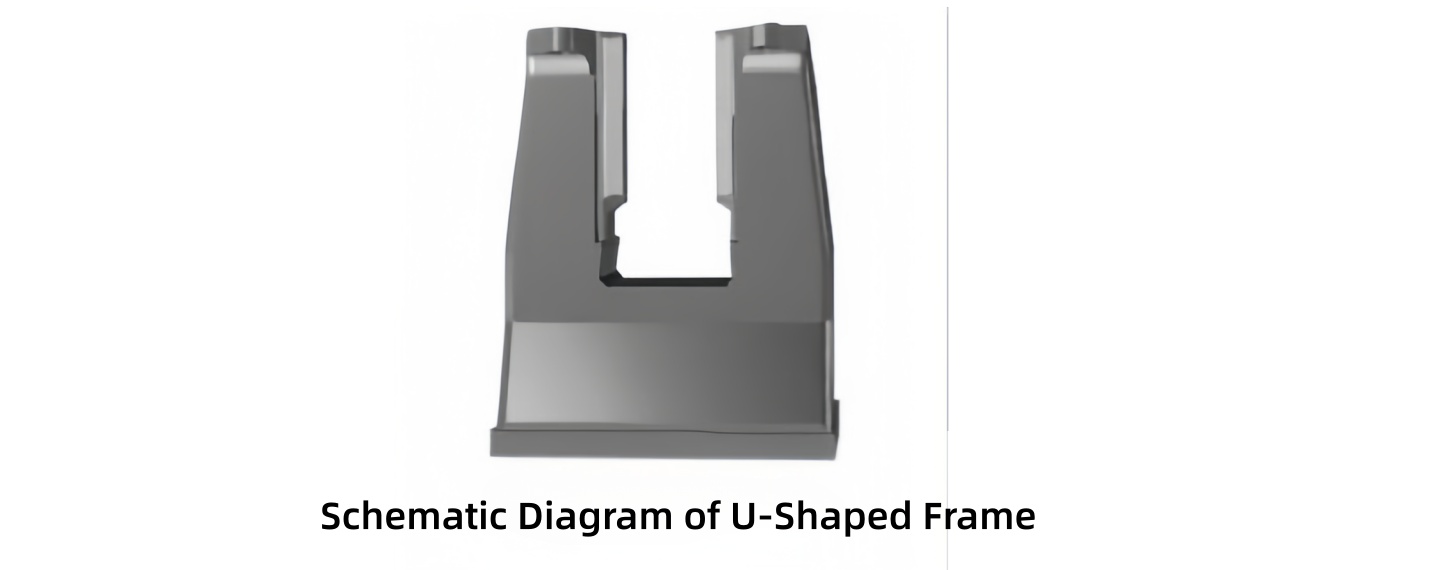
The mechanical structure is compact and rationally designed. The two columns and anvil block are integrated into a unified "U"-shaped frame, fitted with wide X-shaped guide rails. This design prevents the hammer head from jamming while maintaining proper clearance. The inclusion of vibration-damping devices eliminates striking vibrations, contributing to environmental protection and promoting occupational health. An automatic pneumatic safety lock for the hammer head is also installed to prevent accidents and unintended strikes.
The hydraulic system and structural design ensure safety and reliability, enabling high-frequency and high-precision striking. The optimized striking valve design guarantees reliable directional control with minimal wear and excellent sealing. An integrated oil circuit eliminates piping, reducing oil leakage and enhancing aesthetic standardization. A safety valve is included to seal the pressure oil port in case of hammer rod fracture, preventing high-pressure oil leakage and ensuring safe, reliable operation.
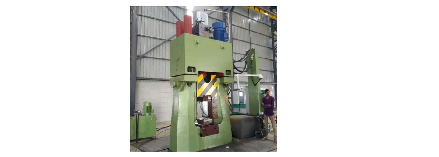
The CNC system controls striking energy and frequency by regulating the closing time of the first-stage pilot valve. A touchscreen is used for data input and output, and a programmer allows arbitrary setting of striking energy. The system also automatically monitors oil temperature and detects faults.
Advantages of the C92KA Series CNC Fully Hydraulic Die Forging Hammer:
◆ Precise Control of Striking Energy
By accurately controlling the closing time of the striking valve, the hammer delivers the exact energy required for forging without generating excess kinetic energy. This significantly extends the lifespan of key components such as the hammer rod, hammer head, and dies. Tests show energy deviation controlled within approximately ±3%. For dies of different heights, the starting time can be easily adjusted to ensure consistent and accurate energy output.
◆ Fast Return Speed
Since the lower chamber of the main cylinder is permanently connected to an accumulator, the hammer retracts rapidly once the upper chamber pressure is released. This shortens die contact time, and combined with precise energy control, extends die service life by more than double.
◆ High Forging Precision
The X-shaped guide rail structure allows for minimal clearance adjustment, resulting in highly precise forgings.
◆ High Material Utilization
Controlled energy enables high precision in pre-forming, uniform flash formation, and eliminates die misalignment. This significantly improves material utilization, laying the foundation for near-net or net-shape forging.
◆ Low Noise
As the hammer’s striking energy is digitally controlled, programming ensures the forging is completed without excess energy, resulting in minimal noise. Traditional hammer operators often rely on auditory cues to determine forging completion, sometimes striking unnecessarily, which generates additional noise.
◆ No Top Impact
Precise calculation and design of damping and throttle holes in the hydraulic system allow the hammer head to buffer smoothly at the top position, eliminating any top impact.
◆ Low Vibration
Digitally controlled striking energy prevents excess energy generation. Combined with German-made "GERB" brand vibration isolators installed at the hammer base, the equipment has minimal impact on surrounding machinery and residential areas.
◆ Environmental Friendliness
Low impact noise and reduced vibration due to integrated damping devices make this an environmentally friendly product.
◆ Stable Forging Quality
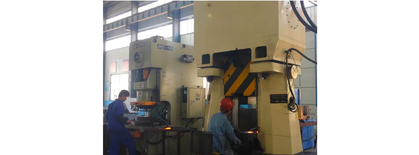
A programmable controller stores forging sequences for various components, allowing consistent striking energy and frequency to be recalled as needed. This eliminates variability from manual operation, ensuring stable forging quality.
The C92KA series CNC fully hydraulic die forging hammer represents currently advanced die forging equipment globally. It is a forging device capable of digitally controlling striking energy and sequence, with a striking energy deviation within ±3%. When paired with suitable robotic automatic loading/unloading, it enables automated production.
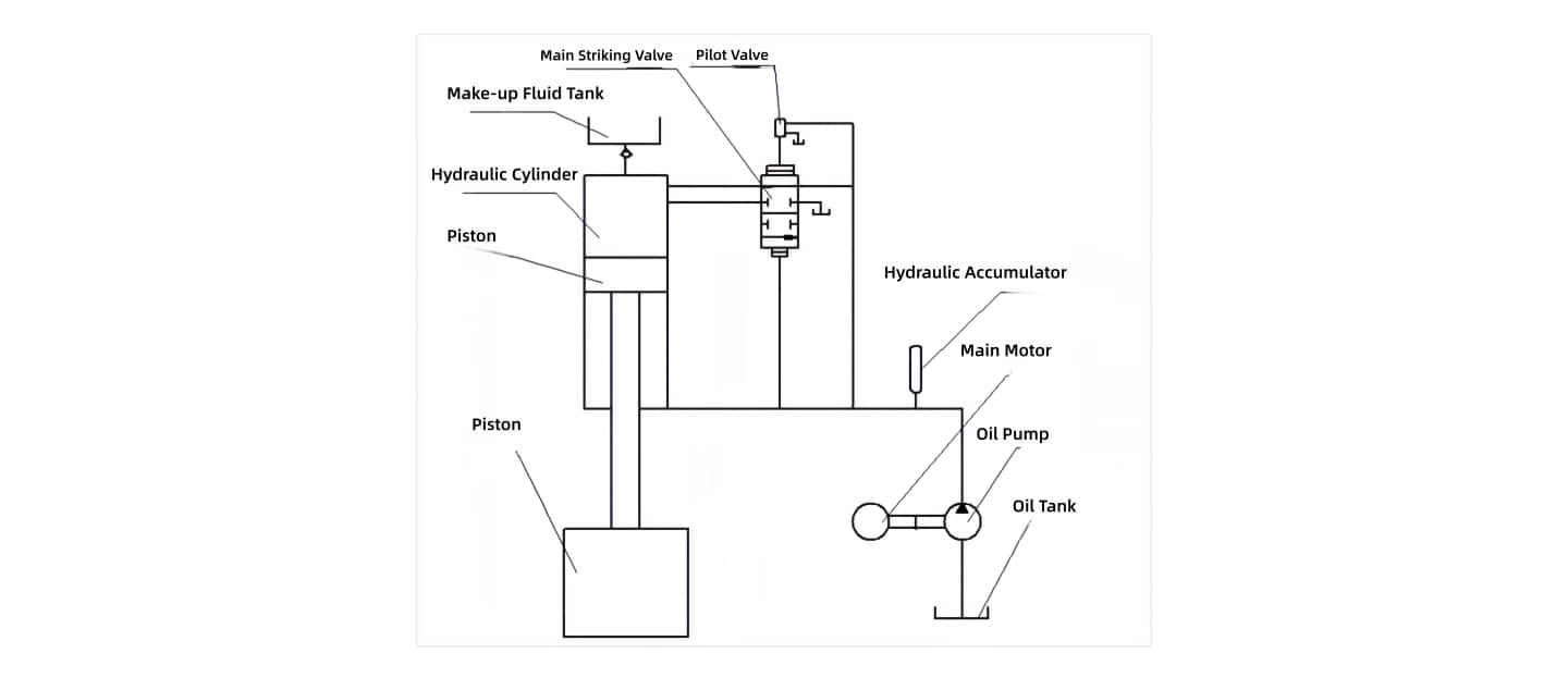
Hydraulic Schematic Diagram of C92KA CNC Fully-Hydraulic Die Forging Hammer
The fundamental principle is: it employs a motor-pump-accumulator transmission system. The lower chamber of the oil cylinder is constantly connected to the accumulator, maintaining constant pressure, while the control system manages the single upper chamber. When the upper chamber inlet valve (also called the striking valve) opens, high-pressure oil from three sources—the pump, the accumulator, and the lower chamber via a differential circuit—enters the upper chamber, driving the hammer head's acceleration downward for the striking stroke. Once the upper chamber pressure is released, the hammer head immediately returns rapidly. Precise control of striking energy is achieved by controlling the duration of the striking valve's closure.
After the main pump starts, it feeds oil to the accumulator, lifting the hammer head. The lower chamber of the main cylinder, constantly connected to the accumulator, holds the hammer head at the upper limit (raised position). For a downward strike, the striking energy is controlled by the closure time of the striking valve, allowing oil from the lower chamber to return to the upper chamber, combining with high-pressure oil from the pump and accumulator to execute the strike. In the suspended state, a pressure sensor controls an unloading valve to open, placing the pump in no-load operation while the accumulator maintains pressure, keeping the hammer head safely raised. The system oil temperature does not rise excessively, saving energy. The main striking valve features high directional change sensitivity and excellent sealing. The overall structure is top-mounted, with integrated assembly and pipeless connections to minimize oil leaks, ensuring high reliability.
Frame Section:
Frame Structure Design:
Utilizes a unitary "U"-shaped frame (or frame with a crossbeam), providing a robust installation and support base for other related components with high rigidity. The lower part is equipped with highly shock-absorbing GERB brand vibration isolation devices, protecting the surrounding environment. The two uprights are fitted with wide "X"-type guide rails, ensuring the hammer head never jams under any conditions. The power unit is mounted on the top, resulting in a small overall footprint. The frame components use high-quality materials, combining the anvil base and the two columns to increase longitudinal and lateral overturning stiffness; this ensures precise guidance for the hammer head, contributing to improved material utilization.
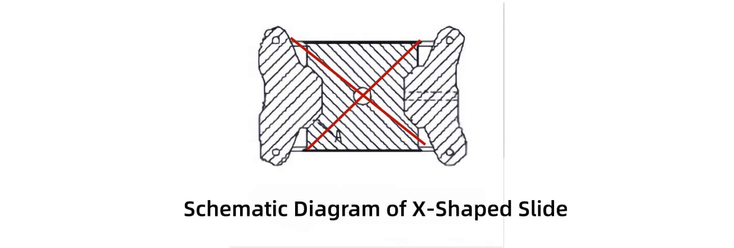
"X"-Type Guide Rail Design:
It is well-known that the hammer head, striking hot workpieces over time, will reach a high overall temperature and expand in volume. Using traditional comb-type guide rails necessitates increasing the clearance between the sliding rail and the hammer head to prevent jamming. However, large sliding clearance in a die forging hammer adversely affects the dimensional quality of precision forgings. To solve this, this product adopts an "X"-shaped guide rail design. When the hammer head heats up, it expands radially. The guiding surfaces are arranged diagonally, preventing a reduction in guiding clearance due to temperature rise. Therefore, the guide rail clearance remains stable, enabling precision forging. Furthermore, widened guide plates create a longer lever arm, reducing the specific pressure on the guide surfaces during off-center strikes. This extends the service life of the guide plates. Consequently, the hammer head guidance is highly precise, the bending moment on the hammer rod is reduced, significantly extending its lifespan.
Hammer Head:
The hammer head is forged by a large, specialized domestic forging plant in China according to national standards, ensuring billet quality. Excellent heat treatment processes and methods guarantee the internal quality and sufficient hardness of the hammer head. Strict non-destructive testing per GB/J4162-94 is conducted before and after heat treatment, preventing substandard products from proceeding.
The guide rail surfaces and dovetail surfaces of the hammer head undergo high-frequency quenching, achieving a hardness of HRC 45-50, enhancing wear resistance of the guide surfaces and preventing deformation or collapse of the dovetail surfaces.
The dovetail slot base employs a smooth arc transition, reducing stress concentration and increasing the strength of the hammer head.
Hammer Rod:
Material: 40CrNiMoA, with mechanical properties reaching δb ≥ 800 MPa, δs ≥ 500 MPa, superior to 40CrNi and 35CrMo.
Strict ultrasonic testing per GB/T4162-92 is performed before and after the hammer rod's heat treatment, ensuring quality.
The piston part of the hammer rod utilizes a copper welding method. The rod itself is made of high-toughness, high-strength material and undergoes special integral heat treatment, extending its service life.
The outer surface of the hammer rod is finished using a rolling process, achieving a surface roughness of Ra ≤ 0.8 µm. Simultaneously, a work-hardened layer forms on the surface, greatly improving wear resistance. This also prevents premature wear and failure of the sealing rings, extending their life.
The hammer rod seal uses imported DICHTOMATIK seals.
Hydraulic Power Unit Section:
The hydraulic system uses a pump-accumulator combined transmission. The lower chamber of the main cylinder is always connected to the accumulator, maintaining constant pressure. The system controls only the upper chamber. Striking energy magnitude is achieved by controlling the closure time of the striking valve, which is a two-stage control valve. The first-stage pilot valve is a 2-position, 4-way directional valve, for which the system demands high quality, requiring both high frequency and high repeatability precision.
A top-mounted structure is used, with internal oil passages enclosed within the main valve block. This integrated design significantly shortens the piping system length compared to side-mounted tank configurations, reducing energy loss by more than half. Furthermore, integration allows for pipeless oil circuit connections, increasing connection reliability.
A safety device is installed in the hydraulic system between the accumulator and the lower chamber. Should the hammer rod fracture at its midsection, it instantly cuts off the oil between the lower chamber and the accumulator, enhancing operational safety.
The oil tank is top-mounted, with a welded body using CO2 shielded welding, complying with JB/T5000.3-1998 and ZQ4000.3-86 "General Requirements for Welding." Surface treatment of the tank body complies with JB/T5000.12-1998.
Post-welding non-destructive testing of the oil tank prevents oil leakage.
The oil tank is enclosed, reducing contamination.
The hydraulic unit casing has local reinforcing ribs for high strength. High-pressure oil passages are unobstructed, offering low flow resistance, minimal heat generation, and improved reliability.
Ejector Section:
The CNC hammer includes an ejector hydraulic station. Ejectors are installed within the die holder, allowing optional automatic ejection or foot pedal-controlled ejection.
Cooling Section:
Electric Refrigeration:
Electric Chiller: Integrates three functions: refrigeration, heating, and precision filtration, featuring remote control and filter clogging alarm, ensuring reliable equipment operation.
When the electric chiller is activated (using an NTC temperature sensor to display detected oil temperature on a digital temperature controller while comparing it to the set point; if oil temperature is higher than the set value), the compressor starts.
Refrigeration begins → Condenser → Expansion valve → Evaporator (heat exchanger). Hydraulic oil → Oil tank → Pump → Evaporator (temperature reduced) → Filter → Oil tank. This cycle continues until the oil temperature reaches the set value. When the oil temperature falls below the lower limit, the controller activates the heater based on the temperature sensor signal.
Lubrication Section:
The automatic lubrication device can also be adjusted by the user via the touchscreen, allowing setting of the lubrication pump's starting frequency and the oil supply duration after startup, customizable based on actual conditions.
Vibration Isolation Foundation Section:
The CNC hammer foundation utilizes GERB vibration isolation devices based on German technology.
Characteristics of the Vibration Isolation Foundation:
(1) The base dimensions are significantly reduced compared to fixed supports, eliminating crossbeams, embedded parts, saving foundation costs and construction time, and easing maintenance.
(2) Excellent vibration isolation effect, attenuating vibration by 80-95%.
(3) Long service life of 30-50 years, potentially requiring no repair.
(4) Simplifies machine leveling, allowing adjustment in case of foundation settlement or tilting.
(5) Reduces vibration levels for the equipment itself and surrounding machinery, lowering the failure rate of hydraulic and electrical control systems.
Composition of the Vibration Isolation Foundation:
The system consists of springs and VISCO® viscous dampers.
Springs provide elastic cushioning, lowering the system's natural frequency. They use helical springs with high load capacity and elasticity.
VISCO® viscous dampers comprise a cylinder filled with high-viscosity fluid and a specially shaped piston inserted into the fluid. The piston's movement within the fluid converts mechanical energy into heat, thereby damping the hammer's impact motion to zero. For impact equipment, they absorb impact energy, allowing the equipment to quickly stabilize after disturbance, ensuring the hammer's impact vibration completely subsides before the next strike, preventing consecutive strike resonance.
Electrical Control Section:
The CNC system uses high-capacity PLCs and touchscreens from Siemens, Germany. The Siemens CNC system features notably: short cycle times, high processing speed, powerful integrated instruction functions suitable for complex tasks, strong communication capabilities, modular structure suitable for dense installation, and high reliability.
To ensure stability in controlling the striking valve, this control system is configured identically to LASCO's. Testing shows striking valve control time accuracy reaches 0.1 ms. A slight drawback is the higher cost. Since adopting the Siemens system, no issues have been found in practice.
The Siemens CNC system is very convenient to operate and adjust. Via the touchscreen, the following can be achieved: adjustment of the equipment's striking energy and various parameters within the full normal data range; programmable strike sequences with a maximum of 9 steps; striking energy adjustable between 0%-100% in 1% increments; strike time accuracy correction; mold height setting range as per technical parameters; oil pressure working pressure/ unloading adjustment range of 195-200 bar; temperature setting range between 25°C to 40°C; automatic guide rail lubrication time range 0-30 seconds, automatic lubrication interval 0-800 strikes; shift production counting function 0-999,999, cumulative counting up to 0-99,999,999 strikes.
The CNC system can include a hydraulic oil cleanliness detection function, with automatic system prompts and alarms for timely replacement, reducing failure rates.
For maintenance convenience, technical documents such as control cabinet wiring diagrams, operator station wiring diagrams, electrical interconnection diagrams, and electrical schematic diagrams can be provided, along with specifications, models, and manufacturers of electrical components.
Main functions of the electrical section include:
The CNC hammer touchscreen has an emergency stop button for immediate halting.
The electrical cabinet features a door-open power cutoff and grounding device, enabling power cutoff when opened, facilitating maintenance and preventing electric shock accidents.
The CNC system can automatically monitor, detect, alarm, and display electrical system overvoltage, overcurrent, and phase loss conditions.
The HMI displays alarm causes, improving troubleshooting time, stores historical alarm data for export and review, and features intelligent alarm display—showing fault point locations for easier resolution.
The CNC system boasts a very large capacity, allowing for free programming and storage of programs
Configuration of Purchased Electrical Components:
The low-voltage section primarily uses Siemens industrial control components. Detailed configuration diagrams and spare parts catalogs can be provided.
High-voltage switches and other components are selected from reputable brands like LG and Schneider; detailed configuration diagrams and spare parts catalogs can be provided.
A dustproof, oil-resistant signal terminal junction box is installed on the tank top. Various signal wires are connected through this box, with oil-resistant, dustproof cable glands at entry/exit points to prevent oil and dust ingress.
All sensors on the equipment and their associated signal cables use PVC oil-resistant, corrosion-resistant wires, protected by metal conduits for reliable and stable operation.
Power supply lines for pressure sensors, signal lines for safety pin sensors, signal lines for hammer head position sensors, and signal lines for filter differential pressure alarms use PVC oil-resistant, corrosion-resistant wires, ensuring longevity and reliability.
Signal lines for safety support sensors and cylinders use oil-resistant, dustproof sleeves, fixed neatly on the frame for clear routing, easy maintenance, and replacement.
Signal lines for the hammer head position sensor use PVC oil-resistant, corrosion-resistant wires, fixed on the frame with protective sleeves and clamps, ensuring reliability.
The electrical cabinet uses dustproof soft gaskets and a professional air cooling unit, with all insulation indexes meeting industrial configuration requirements.
Foot switch components use imported Omron brand, with a durability of 15 million cycles.
Dedicated programs via PLC programming enable automatic air jetting for mold cooling and release.
Motors use domestically renowned brand special vibration-resistant motors, with imported NSK brand bearings, reducing failure rates.
(1) The hydraulic principle is essentially the same as that of a complete CNC hammer, but the overall design philosophy follows four principles: "Large Hammer Head, Low Oil Speed, Short Stroke, High Frequency." Therefore, considering the unique characteristics of steam-air or electro-hydraulic hammers (long stroke, small guide rail spacing, small connecting plate area making it difficult to install the complete CNC power head, etc.), the retrofit design has the following features compared to a new machine:
For retrofitting 1-ton and 2-ton old hammers, a large integrated top-mounted oil tank is used, and a larger connecting plate is installed. For retrofitting 3-ton and above old hammers, a main/auxiliary tank setup is used (main tank top-mounted on the original connecting plate, with floor-standing frames on both sides of the frame supporting two auxiliary tanks). All connections between main and auxiliary tanks use flexible structures.
A new hammer head with an "X"-type guide rail structure is installed, and the frame guide rails are also replaced. This achieves improved off-center load resistance and forging precision.
Due to the excessive stroke of the old hammer, an upper die holder is installed on the hammer head. This both reduces the effective stroke and protects the hammer head dovetail.
Depending on whether the user requires an ejector device, a decision is made on replacing the die holder and configuring an ejector hydraulic station.
Since safety pin holes cannot be machined into the old frame, an additional hammer head safety support is installed. The safety support is interlocked with the striking valve, enhancing operator safety.
The performance of the retrofitted hammer essentially meets that of a complete new CNC hammer, overcoming various drawbacks of the original old hammer, thereby elevating the product grade.

Receive the news that you are interested in.