
The automotive connecting rod forging process is typically based on hot closed-die forging, with the exact process route depending on the material grade, part geometry, billet size, required production volume and equipment configuration. For a forging equipment buyer, the critical question is not simply which machine has sufficient nominal capacity, but whether the complete forming system can provide stable deformation, repeatable die filling and an appropriate production cycle.
Quick Answer
The automotive connecting rod forging process generally includes material preparation, billet cutting, billet heating, preforming or blocking, final closed-die forging, trimming, cooling and subsequent heat treatment, inspection and machining.
The most important process controls are billet weight and dimensions, heating temperature and uniformity, transfer time, die temperature, material flow, forging reduction, die filling, flash formation, dimensional accuracy and cooling conditions. Equipment selection should be based on the workpiece and process requirements rather than machine type alone.
Depending on the workpiece, production target and forming route, a forging production system may incorporate a forging press, electric screw press, forging hammer, trimming equipment, heating system and automated transfer equipment. AYANK's equipment portfolio includes forging hammers, electric screw presses, forging presses, roll forging equipment and automatic forging production lines, allowing equipment selection to be considered as part of the overall process rather than as an isolated machine purchase.
1. What Is the Automotive Connecting Rod Forging Process?
Connecting rod forging is a metal forming process in which a heated steel billet is plastically deformed between dies to produce the characteristic geometry of the connecting rod. The forging route is designed to establish the required shape while controlling the direction and distribution of metal flow.
Unlike machining a connecting rod from a solid block, forging can establish a shaped material structure that follows the major geometry of the component. However, the quality of the final forging depends strongly on how the billet enters each forming stage and how the material fills the die cavity.
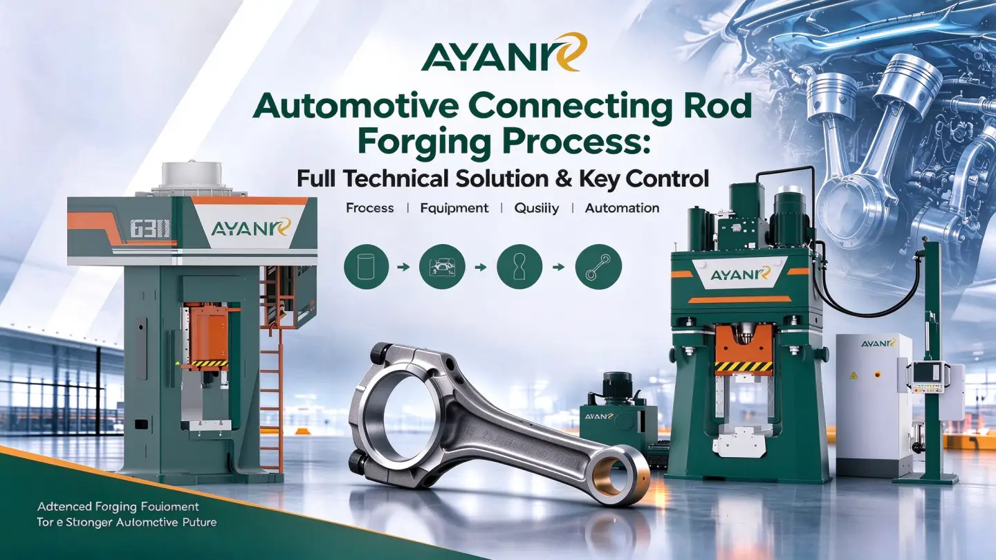
A typical process flow can be represented as:
- Raw material preparation
- Billet cutting
- Billet heating
- Preforming or blocking
- Final die forging
- Trimming and, where required, piercing
- Controlled cooling
- Heat treatment
- Surface cleaning and inspection
- Machining and final dimensional inspection
Not every connecting rod requires exactly the same sequence. The appropriate route depends on the component drawing, material, starting billet and required production performance.
2. Connecting Rod Forging Process Flow
Understanding the complete process flow is essential before selecting the forging machine. A machine that performs well at the final forming operation may still be unsuitable for the complete production system if the preceding heating, transfer or preforming stages cannot maintain the required process window.
2.1 Raw Material and Billet Preparation
The first stage is to prepare the forging stock according to the material specification and required billet dimensions. The billet must provide enough material for complete die filling while allowing for the material removed during trimming and subsequent machining.
Billet weight is particularly important. An undersized billet can result in incomplete die filling or insufficient machining allowance. An oversized billet can increase flash, forming load and material consumption.
For an equipment evaluation, the buyer should therefore provide the material grade, billet diameter or cross-sectional dimensions, billet length and billet weight rather than only the finished connecting rod dimensions.
2.2 Billet Heating
Temperature stability is the most critical factor affecting connecting rod forging quality. Automotive connecting rods are mostly made of alloy structural steels such as 40Cr and 42CrMo, with a standard forging temperature range of 1150 °C–1250 °C.
Medium-frequency induction furnaces are used to achieve uniform and rapid heating, avoiding local overheating or underheating. Overheating can cause coarse grain structure and reduced fatigue strength; underheating increases deformation resistance, leads to insufficient die filling, and induces forging cracks. The core control requirement is that the billet temperature must be consistent throughout, with the temperature difference controlled within ±20 °C to ensure uniform metal deformation.
The heating system and forging equipment must therefore be considered together. If the transfer time between the heating station and forging machine is long or inconsistent, the workpiece temperature at the die can vary even when the furnace temperature itself is stable.
Important variables include:
- Initial billet temperature
- Heating uniformity
- Soaking time
- Transfer time
- Scale formation
- Temperature loss during transfer
- Consistency between successive billets
2.3 Preforming or Blocking
For connecting rods with complex geometry, a preforming operation can help distribute material before the final die-forging stage. The purpose is to move the required volume of material toward the regions that will form the big end, shank and small end of the connecting rod.
A properly designed preform can reduce the amount of uncontrolled material movement required during final forging. It can also help improve die filling and make the final forming operation more repeatable.
The exact preforming method depends on the part geometry and production route. In some applications, dedicated preforming dies are used; in others, rolling or other preliminary forming operations may be considered before the final forging stage.
2.4 Final Closed-Die Forging
The final forging operation establishes the main geometry of the connecting rod. The heated preform is positioned in the finishing die and subjected to controlled deformation until the die cavity is substantially filled.
This stage requires close control of several interacting factors:
- Workpiece temperature
- Preform geometry
- Die geometry
- Forging stroke or energy
- Deformation speed
- Material flow
- Die alignment
- Lubrication and die condition
The objective is not simply to achieve a visually complete forging. Stable material flow and repeatable filling are important because local defects or dimensional variation may affect later machining and component performance.
2.5 Trimming and Piercing
After closed-die forging, excess material in the flash region normally has to be removed. Depending on the component design, additional piercing or related operations may also be required.
Trimming is therefore an important part of the overall connecting rod forging line rather than an afterthought. The forging and trimming operations should be evaluated together when determining production flow, workpiece transfer and automation requirements.
2.6 Cooling and Heat Treatment
After forming and trimming, the connecting rod forgings must be cooled under controlled conditions appropriate to the selected material and downstream process. Subsequent heat treatment may be required to obtain the specified mechanical properties and metallurgical condition.
Cooling conditions should not be considered independently from the forging process. The thermal history of the component begins during billet heating and continues through forging, transfer and cooling. Consequently, process consistency across these stages is important for repeatable production.
3. Key Process Controls in Connecting Rod Forging
For production engineers and equipment buyers, the most useful way to evaluate a connecting rod forging process is to identify the variables that directly affect repeatability.
| Control Factor | Why It Matters |
|---|---|
| Billet weight | Determines whether sufficient material is available for die filling and machining allowance. |
| Billet dimensions | Affects initial material distribution and the subsequent preforming operation. |
| Heating temperature | Influences material flow and forging resistance. |
| Temperature uniformity | Helps maintain consistent deformation behavior from billet to billet. |
| Transfer time | Affects the actual workpiece temperature when it reaches the die. |
| Preform geometry | Controls how material is distributed before final forging. |
| Die condition | Influences filling, dimensions, surface condition and die life. |
| Forging energy or force | Must be appropriate for the material, geometry and deformation stage. |
| Alignment | Helps maintain consistent die contact and forging geometry. |
| Cooling conditions | Influence the thermal and metallurgical condition of the forged component. |
These variables also explain why equipment selection should not begin with a machine model alone. The correct configuration depends on the actual workpiece, process sequence and production requirements.
4. Why Material Flow Matters in Connecting Rod Forging
Material flow is one of the central engineering considerations in closed-die connecting rod forging. The forging dies must guide the heated material into the required sections of the cavity without creating unfavorable local deformation conditions.
The connecting rod has multiple functional regions with different geometric requirements. The big end and small end require sufficient material volume, while the shank must achieve the required cross-sectional shape without unnecessary excess material.
A poorly designed preform can force the finishing operation to perform excessive material redistribution. This can increase forming requirements and may contribute to inconsistent filling or flash formation.
For this reason, process development should consider the billet, preform and finishing die as a connected system.
5. Choosing Forging Equipment for Connecting Rod Production
Once the process route has been established, the next question is how to select the forming equipment. The choice should be based on the workpiece and required process characteristics rather than on nominal machine capacity alone.
For connecting rod production, the evaluation may include forging hammers, mechanical or electric screw presses, hydraulic forging equipment and integrated automatic forging systems. Each technology provides a different forming behavior and must be matched to the workpiece, die design and production requirements.
| Evaluation Factor | What the Buyer Should Define |
|---|---|
| Workpiece | Connecting rod drawing, material grade and finished forging geometry |
| Starting stock | Billet dimensions and billet weight |
| Production | Required production volume and target cycle |
| Process route | Number of forming stages and trimming requirements |
| Automation | Manual, semi-automatic or fully integrated material transfer |
| Die system | Preforming, finishing and trimming die requirements |
| Factory conditions | Available layout, utilities and installation requirements |
For projects where an electric screw press is appropriate, AYANK's J58KA Electric Screw Press and J58ZKA Servo Direct Drive Electric Screw Press are relevant product families to evaluate against the actual connecting rod process requirements. No machine should be selected from the model name alone; the final configuration should be confirmed against the workpiece and process data.
The next stage is to compare the forming technologies and identify which process characteristics matter when developing a connecting rod production line.
6. Forging Hammer vs Electric Screw Press for Connecting Rods
The choice between a forging hammer and an electric screw press should be based on the required forming behavior, workpiece geometry, die design, production method and automation strategy. There is no universal machine type that is appropriate for every connecting rod forging application.
| Factor | Forging Hammer | Electric Screw Press |
|---|---|---|
| Primary forming characteristic | Impact-based deformation | Controlled screw-driven forming action |
| Process suitability | Can be considered for forging operations requiring repeated impact forming | Can be considered where controlled press forming and repeatable process conditions are required |
| Process development | Requires evaluation of impact energy, die design and workpiece temperature | Requires evaluation of forming energy, stroke, die design and process cycle |
| Automation | Can be integrated into automated forging systems | Can be integrated with automated material handling and production lines |
| Buyer priority | Match impact characteristics to the workpiece and die system | Match forming characteristics and control requirements to the workpiece and production target |
For a production project, this comparison should be followed by an application-specific engineering assessment. The machine type should be selected only after the workpiece drawing, material, billet conditions, forming stages and production target have been reviewed.
For background information about forging equipment, buyers can also refer to AYANK's existing resources on what forging is and forging hammers.
7. Key Equipment in an Automotive Connecting Rod Forging Line
A connecting rod production line normally involves more than the main forming machine. The complete system may include material preparation, heating, forming, trimming, cooling, inspection and material-transfer equipment.
7.1 Billet Cutting Equipment
The billet-cutting stage establishes the starting volume for the forging process. Cutting accuracy matters because variations in billet weight can directly affect material distribution during subsequent forming.
7.2 Heating System
The heating system must provide a consistent workpiece temperature suitable for the selected material and forging route. The interface between heating and forming is particularly important in an automated line because transfer time becomes a process variable.
7.3 Preforming Equipment
Where the connecting rod geometry requires multiple forming stages, preforming equipment or an additional forming operation may be used to establish an appropriate material distribution before final forging.
7.4 Main Forging Machine
The main forging machine performs the primary forming operation. Depending on the process, this may be a forging hammer, electric screw press, forging press or another forming system selected according to the workpiece requirements.
7.5 Trimming Equipment
After final forging, excess flash must generally be removed. The trimming operation should be considered when determining the line layout, cycle time and transfer system.
7.6 Transfer and Automation System
Automatic transfer becomes increasingly important as production volume increases. A production line may require coordinated movement between heating, forming, trimming and cooling stations while maintaining the required workpiece sequence and transfer timing.
AYANK's product portfolio includes automatic forging production equipment as well as individual forming machines. For a new project, the appropriate approach is to evaluate whether the customer needs a standalone forging machine or an integrated production solution.
8. Common Quality Problems in Connecting Rod Forging
Forging defects should be evaluated in relation to the complete process rather than attributed to the main forging machine automatically. Several process variables can interact to produce the same visible problem.
8.1 Incomplete Die Filling
Incomplete filling can be associated with insufficient material volume, unsuitable preform geometry, inadequate workpiece temperature, inappropriate forming conditions or die-related issues.
The first step is therefore to identify where the cavity is not filling and determine whether the root cause is material distribution, thermal condition, die geometry or forming capacity.
8.2 Excessive Flash
Flash is expected in many closed-die forging operations, but excessive flash can indicate inefficient material distribution or an unsuitable starting billet volume. Excessive flash also increases material consumption and may increase trimming requirements.
8.3 Dimensional Variation
Dimensional variation can result from changes in billet temperature, billet weight, die condition, machine alignment, forming conditions or cooling behavior. Stable production therefore requires control of the complete process window.
8.4 Surface Defects
Surface quality can be influenced by billet condition, scale formation, die surface condition, lubrication and the thermal history of the workpiece. Surface defects should be investigated together with upstream heating and material preparation.
8.5 Cracking
Cracking requires particular attention because it may involve material condition, forging temperature, deformation behavior, geometry or excessive local strain. The appropriate corrective action depends on the actual failure mechanism and should be established through process analysis rather than machine selection alone.
9. How to Control the Connecting Rod Forging Process
A practical process-control strategy should identify the variables that have the greatest influence on forging repeatability and establish inspection or monitoring methods around them.
| Process Stage | Key Variables to Monitor | Typical Control Objective |
|---|---|---|
| Material preparation | Material grade, billet dimensions, billet weight | Maintain consistent starting material |
| Heating | Temperature, heating uniformity, heating time | Provide repeatable forging conditions |
| Transfer | Transfer time, workpiece temperature loss | Keep the workpiece within the intended process window |
| Preforming | Preform dimensions and material distribution | Prepare appropriate stock for final forging |
| Final forging | Machine conditions, die alignment, forming energy or force | Achieve consistent die filling |
| Trimming | Part positioning, die condition, flash removal | Produce consistent trimmed forgings |
| Cooling | Cooling conditions and transfer sequence | Maintain controlled thermal history |
| Inspection | Dimensions, surface condition and required quality characteristics | Identify process variation before downstream machining |
The most effective control strategy is normally established during process development and then transferred into production documentation, machine settings, inspection procedures and maintenance standards.
10. Connecting Rod Forging Automation
Automation can improve material flow and production consistency when the individual operations have already been properly defined. It should not be treated as a substitute for process development.
An automated connecting rod forging line may coordinate:
- Billet loading
- Heating
- Workpiece transfer
- Preforming
- Final forging
- Trimming
- Cooling
- Part transfer
- Inspection or quality-control operations
The degree of automation should be determined by production volume, required cycle, labor strategy, factory layout, process stability and the customer's investment objectives.
For a new automated forging project, the equipment supplier should understand the entire process route rather than receiving only a request for a machine with a nominal capacity.
11. Buyer Checklist for a Connecting Rod Forging Machine
Before requesting a technical proposal, the buyer should prepare sufficient information for the equipment supplier to evaluate the actual forming process.
- Final connecting rod drawing
- Material grade and material standard
- Billet dimensions
- Billet weight
- Finished forging weight
- Forging temperature range or existing heating process
- Required production volume
- Target cycle time, if established
- Existing forging process
- Number of forging stages
- Die information, if already available
- Required trimming operation
- Automation requirements
- Available factory layout
- Electrical and utility requirements
- Installation country
Providing this information allows the equipment supplier to evaluate the process as a system instead of making a machine recommendation from incomplete information.
12. How AYANK Can Support Forging Equipment Selection
For connecting rod and other automotive forging applications, equipment selection should begin with the workpiece and process route. AYANK approaches forging equipment selection around the forming application, with equipment families covering forging hammers, electric screw presses, forging presses, roll forging equipment and automatic forging production lines.
Depending on the required process, equipment evaluation may involve a single forming machine or a broader production-line configuration. The appropriate solution should be established from the actual workpiece drawing, material, billet conditions, production target and automation requirements.
This workpiece-based approach is particularly important for automotive components because a machine that is suitable for one forged component may not provide the same process solution for another component with different geometry, material volume or production requirements.
Planning a New Connecting Rod Forging Project?
Send AYANK your workpiece drawing, material grade, billet dimensions, billet weight, production target, existing process and automation requirements for equipment selection and project evaluation.
13. Conclusion: Build the Forging Process Around the Workpiece
The automotive connecting rod forging process is a sequence of interconnected operations rather than a single forging-machine operation. Billet preparation, heating, preforming, final die forging, trimming, cooling and inspection all contribute to the final result.
The most important controls include billet consistency, heating conditions, transfer time, material distribution, die condition, forming parameters and cooling conditions. These variables should be evaluated together when developing the production process.
For equipment buyers, the practical starting point is the connecting rod itself: provide the drawing, material, billet information, production target and automation requirements, then evaluate the appropriate forming technology and line configuration around those requirements.
Frequently Asked Questions
What is the typical automotive connecting rod forging process?
A typical route includes billet preparation, cutting, heating, preforming, final closed-die forging, trimming, cooling, heat treatment, inspection and subsequent machining. The exact sequence depends on the connecting rod design, material and production requirements.
Why is billet weight important in connecting rod forging?
Billet weight determines the amount of material available to fill the forging dies and provide the required machining allowance. Variations in billet weight can affect material distribution, flash formation and dimensional consistency.
What are the key controls in connecting rod forging?
Important controls include billet dimensions and weight, heating temperature and uniformity, transfer time, preform geometry, die condition, machine forming conditions, alignment, trimming and cooling conditions.
How do I choose forging equipment for connecting rods?
Equipment should be selected from the workpiece drawing, material grade, billet dimensions, forging stages, production target, die system and automation requirements. The appropriate machine type should be confirmed through an application-specific engineering evaluation.
Can connecting rod forging be automated?
Yes. Depending on production requirements, billet handling, heating, transfer, forging, trimming, cooling and other operations can be integrated into an automated forging production line. The automation level should be determined by the process route and production objectives.
What information should I provide when requesting a connecting rod forging machine quotation?
Useful information includes the connecting rod drawing, material grade, billet dimensions and weight, finished forging weight, forging temperature, production volume, target cycle, existing process, die information, automation requirements, factory layout and installation requirements.