The C66YA series fully hydraulic open-die forging hammer (also known as an electro-hydraulic hammer) and its fully hydraulic power unit are next-generation products developed by AYANK FORGING Machinery Industry Co., Ltd., serving as upgrades to traditional pneumatic-hydraulic hammers. AYANK FORGING holds patented technologies for these systems. Key advantages include energy efficiency, environmental friendliness, high productivity, low failure rates, improved working conditions, and reduced labor intensity for operators .
Steam/air-driven forging hammers exhibit primary energy utilization rates below 2% (sometimes as low as 0.2%), whereas the fully hydraulic electro-hydraulic power unit achieves up to 20% primary energy utilization. By replacing inefficient air-powered systems with fully hydraulic technology, energy savings exceed 90%, while restoring equipment precision and enhancing forging capacity. This significantly reduces energy consumption and production costs .
The operational principle of fully hydraulic drive electro-hydraulic hammers determines their advantages of sufficient energy, high frequency, no die sticking, and low failure rate:
Eliminates oil-gas cross-leakage and air leakage issues in the hammer piston rod, as well as oil-gas cross-leakage and air leakage at the lower end of the cylinder liner.
During the return stroke, there is no back pressure in the upper chamber of the piston, which increases the return speed and striking frequency, thereby significantly improving productivity.
Removes the main cylinder air distribution system and auxiliary air tank, enabling simplified design.
The working environment for the piston rod seals is improved, and the sealing requirements for the piston rod are reduced, greatly extending the seal lifespan and significantly reducing replacement frequency.
Since the lower chamber of the piston typically operates under high pressure, the hammer head returns without delay after striking, with minimal die sticking time, thereby extending the lifespan of the die (anvil block) and facilitating workpiece handling by operators.
Fewer factors influence the system pressure, allowing for precise control of striking energy.
II. Detailed Description of the C66YA Fully Hydraulic Open-Die Forging Hammer
1. Hydraulic Principle
The C66YA fully hydraulic open-die forging hammer is driven by a motor-powered high-pressure oil pump that supplies high-pressure oil to actuate the hammer head. The equipment operates as a self-contained system, independent of boilers or air compressors, and is not limited by the presence or pressure of air—enabling operation whenever power is available.
The C66YA fully hydraulic open-die forging hammer refers to a hydraulic hammer in which both the striking and return strokes—i.e., the upward and downward travel of the ram—are driven by hydraulic oil. The system operates on the principle that the lower chamber of the ram piston is constantly connected to high-pressure oil, while the transition between high and low pressure in the upper chamber of the piston controls the striking and return motions.
When high pressure is applied to the upper chamber of the ram piston, the lower chamber remains under high pressure. The high-pressure oil acts simultaneously on the circular area at the top of the ram piston and the annular area at the bottom. Due to the difference in surface areas, a downward force is generated, which—combined with the weight of the falling components—enables the downward strike. Concurrently, oil from the lower chamber returns to the upper chamber through connected oil passages.
When the pressure in the upper chamber is released to a low level, the return force generated by the constant high pressure acting on the annular area of the lower chamber overcomes the weight of the falling parts and associated frictional forces, thereby achieving the return stroke.
2. Structural Overview
The hydraulic forging hammer adopts a split design between the mainframe and the hydraulic power unit. Specifically, the power head (main unit) is mounted on the frame, while the hydraulic power unit is placed on the ground, with the two connected via pipelines. The hammer head, frame, and guide rails feature an "X"-type guide rail configuration. Maintenance is convenient, with the normal time for repairing or replacing wear parts not exceeding 4 hours, except for some specific maintenance points.
2.1 Structure of the Hydraulic Power Head System
The hydraulic power head structure mainly consists of the cylinder block beam, main cylinder, accumulator, ram, main control valve, cushion cylinder, cylinder liner, lower seal head, and hammer head, among other components.
The power head is fixed to the frame via connecting bolts, through buffer pads and preload springs.
A hydraulic pump driven by the motor supplies pressurized oil at approximately 10 MPa to the accumulator and main cylinder. The flow and direction of the pressurized oil are controlled by the main operating valve. The pressurized oil constantly acts on the annular area of the ram piston's lower chamber, enabling the hammer head to achieve a rapid return stroke automatically after each strike without delay. This prevents die sticking and helps extend die life.
2.1.1 Cylinder Block Beam
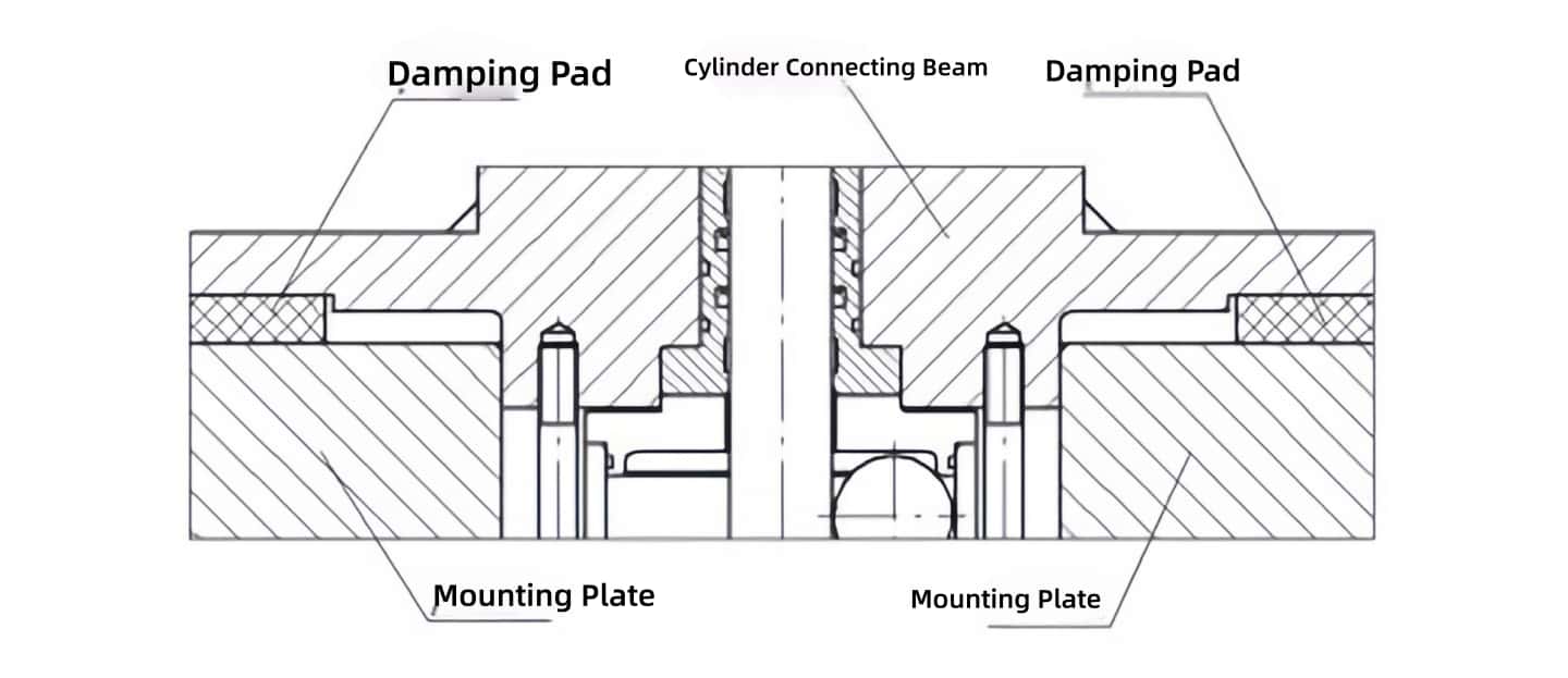
The cylinder block beam is constructed by welding 16Mn steel plates, followed by post-weld annealing to relieve stress. All components of the power head are mounted on this beam. It incorporates an oil drain recovery valve and is secured to the frame via connecting bolts, buffer pads, and preload springs.
To enhance positioning and ensure the stability of the ram's movement center, the lower part of the cylinder block beam is designed with a positioning boss that fits with a small clearance in the center hole of the connecting plate. This provides positioning during operation, restricting horizontal displacement of the beam, thereby ensuring the concentricity of the main cylinder, lower seal, and hammer head guide rails. Two rectangular, one-piece damping pads are used, increasing the contact area and significantly improving the overall stability of the cylinder block beam.
Cylinder Connecting Beam Positioning
2.1.2 Main Cylinder and Cylinder Liner
The lower part of the main cylinder is made from a single forging. The upper cylinder body is welded to the lower part, with the middle section reinforced by the welded structure of the cylinder block beam. The lower end of the cylinder liner is positioned and installed within the main cylinder, while its upper end is located and secured by the lower seat of the cushion cylinder. The oil port at the lower end of the liner connects the main cylinder to the constant-pressure oil passage of the ram's lower chamber.
The cylinder liner is made of 45# steel, quenched and tempered to HB260-280. The internal surface undergoes precision machining, grinding, and roller burnishing, ensuring tensile strength, improving the inner surface's fatigue resistance, increasing wall thickness, and preventing cylinder deformation due to eccentric or overload conditions.
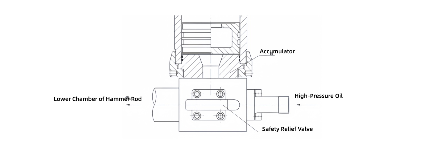
2.1.3 Accumulator
The lower oil port of the accumulator is constantly connected to the high-pressure oil in the ram's lower chamber, ensuring rapid fluid replenishment during striking and timely return of the hammer head after the strike. The accumulator's lower end is positioned via a spigot and fastened with bolts to the accumulator base. Its middle section is secured and prevented from loosening via a tapered surface clamp, with the accumulator connected via a threaded pressure plate and tightened with bolts. The upper end of the accumulator is equipped with a gas circuit interface and Hall sensors.
Multiple Hall sensor elements are employed to control the unloading valve in stages, reducing hydraulic system shock and protecting the equipment. Imported Hall sensors with good anti-vibration performance and strong magnets are selected to increase the sensing range. The Hall sensor bracket features an external pressure-mounted structure, allowing the entire Hall sensor assembly to be installed from above the accumulator top cover, facilitating easy disassembly and maintenance.
Unloading Schematic Diagram for Three-Stage Hall Switch Element Sectional Control Unloading Valve
2.1.4 Main Control Valve
This hydraulic hammer uses a pilot-operated servo-controlled main striking valve (High-Frequency Fully Hydraulic Electro-Hydraulic Hammer, Patent No.: ZL201020273919.5). It combines the characteristics of spool valve operation and poppet valve sealing, enhancing the controllability and sealing of the valve port opening/closing. It features fast response, high flow capacity, reducing internal leakage and heat generation within the system. It enables functions such as striking, return, slow up, slow down, holding the hammer at any position (sliding distance ≤ 10mm within 5 seconds), and continuous striking with different strokes and frequencies.
The mating surfaces inside the main control valve undergo nitriding treatment, providing higher surface hardness, wear resistance, corrosion resistance, and fatigue resistance. The valve body is rationally designed with pressure-equalizing grooves, and a 10μm pipeline filter is added at the pilot inlet to reduce the failure rate of the main control valve sticking.
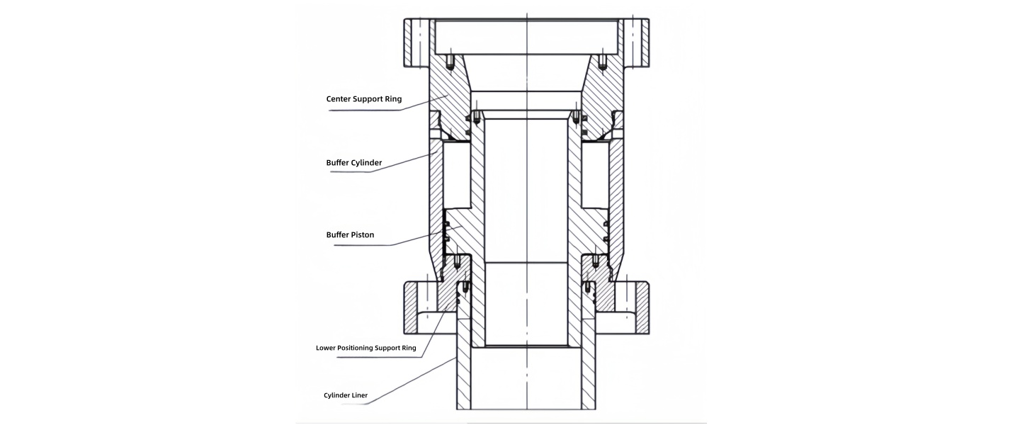
2.1.5 Cushion Cylinder
The hammer employs a reliable hydraulic anti-overtopping device (Anti-Overtopping Hydraulic Electro-Hydraulic Hammer, Patent No.: ZL200610114757.9). It allows the hammer head to stop smoothly at the upper limit during high-speed return without severe impact noise, preventing damage to the main valve and major oil leakage incidents. The cushion cylinder is located at the upper end of the cylinder liner, which is also above the ram's top dead center. When the hammer head rises rapidly to the top dead center, the buffer head at the top of the ram first enters the cushion piston, achieving throttle buffering. When the piston rod fully contacts the cushion piston, hydraulic resistance buffering brings it to a stop at the upper limit, achieving a soft stop.
Schematic Diagram of the Hydraulic Anti-Collision Top Device
2.1.6 Lower Seal Head
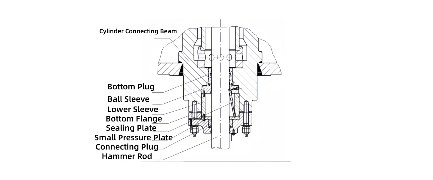
The lower seal head features a guiding and positioning sleeve design. During off-center forging impacts, the guiding sleeve transfers the off-center force to the connecting plate, so the lower plug and seal bolts do not bear the off-center load. This extends the seal life of the lower plug and prevents loosening of the seal bolts. Additionally, the guiding length of the lower plug is increased, and a dual high-pressure/low-pressure isolation seal is adopted. This effectively reduces the impact of eccentric loads and overloads on the ram and seals, extending their service life. An oil leakage collection device is also provided.
The lower seal head incorporates a German-made flap-type ram fracture protection device. If the ram suddenly fractures in the middle, the flap automatically drops down, isolating the lower seal head from the outside, preventing high-pressure oil from the ram's lower chamber from spilling and causing fire. Simultaneously, the ram fracture protection sends an alarm signal, promptly cutting off all power to prevent major accidents.
Schematic Diagram of the Lower Seal Anti-Leak Oil Device
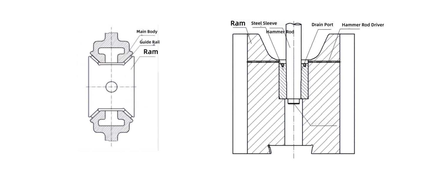
2.1.7 Falling Parts
The falling parts consist of the hammer head, ram, and taper sleeve. The ram and taper sleeve are connected via a tapered surface with a 1:25 taper.
The hammer head and frame use an "X"-type guide rail (CNC Fully Hydraulic Die Forging Hammer Hammer Head Guide Rail, Patent No.: ZL200520128396.4). This rationally increases the guiding length of the hammer head, improves resistance to off-center loads and impact, eliminates guide rail scoring and hammer jamming, thereby enhancing ram life and forging precision. It also allows hammer head replacement without disassembling the cylinder block beam; only the ram needs to be removed. The hammer head is made of 42CrMo forged steel, quenched and tempered to HB240-280. The four guide rail surfaces and dovetail surface are surface hardened to HRC43-53, precision milled to a surface finish of 1.6. The perpendicularity of the guide rail surfaces to the dovetail base is ≤0.05, and symmetry to the centerline is ≤0.05.
The hydraulic power head and hammer head are connected via a ram capable of elastic bending deformation, which flexibly absorbs inevitable tilting motion within guide rail clearances and eccentric loads. The ram is made of 40CrNiMoA forged steel, heat treated to HRC32-38, with piston-ram concentricity ≤0.02. The ram surface is roller burnished, achieving a surface finish of 0.4, increasing ram life.
The hammer head and ram are connected using a single-taper steel sleeve direct-insertion structure designed based on tribology principles (CNC Fully Hydraulic Die Forging Hammer Hammer Head and Ram Connection Device, Patent No.: ZL200520128395.X). A copper sheet is added between the ram and taper sleeve. The hammer head core has a disassembly hole, so when removing the hammer head, only an ejector pin needs to be installed in the center hole. The hammer head quickly descends, allowing the ram to be pulled out.
Schematic Diagram of the Single-Taper Straight-Insertion Hammer Head and Rod Connection
2.2 Mainframe Section
The mainframe section primarily consists of the frame (left and right columns), guide plates, connecting plate, anvil block assembly, maintenance platform, and operating mechanism.
2.2.1 Frame
The frame material is ZG35, annealed for stress relief. The flatness of the assembly surface between the hammer arm and anvil base is ≤0.1/1000. The parallelism between the upper and lower assembly surfaces of the hammer arm is ≤0.1/1000. The perpendicularity of the guide rail mounting surface to the lower surface of the hammer arm is ≤0.1/1000. The surface finish of all mating surfaces is not less than 3.2.
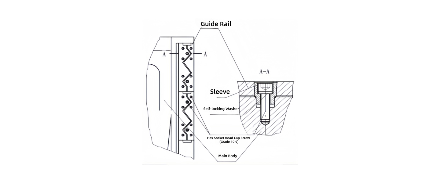
The adjustable guide plate is positioned on three sides within a frame groove, secured with shear-resistant locating sleeve bolts and self-locking washers to prevent loosening. The guide plate material is 40Cr, nitrided to a hardness of HRC50-55, with a surface finish of 1.6 for surfaces mating with the hammer head.
Positioning and Fastening of the Guide Plate to the Machine Body
2.2.2 Connecting Plate
The connecting plate is the intermediate connecting piece between the frame and the cylinder block beam. It is positioned relative to the lower seal head of the cylinder block beam with a small clearance fit. A one-piece damping pad is placed in between to absorb micro-vibrations, increasing the stability of the power head. It is positioned longitudinally to the frame via a groove and adjusted with wedges, and positioned laterally via a widened flat key. This ensures concentricity of the hammer head and guide rails. These components are fastened together via connecting bolts and preload springs, meeting the requirements for motion rigidity and impact absorption during hammer operation.
2.2.3 Anvil Block Assembly
The anvil block assembly consists of the lower anvil block, anvil cushion, upper and lower anvil bases, and wedges.
The anvil base material is ZG25, cast by a large domestic foundry, annealed for stress relief, and inspected by non-destructive testing to ensure component quality.
The anvil cushion material is 45# forging. The upper and lower anvil blocks are made of 42CrMo forging.
2.2.4 Maintenance Platform
Due to significant vibration during hammer operation, a separate maintenance platform independent of the frame is provided. The platform is equipped with a caged ladder and guardrails. The middle section of the front and rear footplates of the platform has a removable flap, facilitating crane handling of workpieces and auxiliary anvil changes (handling, wedge tightening, etc.). The platform is welded and constructed robustly to withstand accidental impact from the crane's main hook, preventing damage to the hydraulic control system.
2.2.5 Operating Mechanism
A foot pedal and manual interconnected operating mechanism is provided. Both operating mechanisms should be easily removable to prevent interference when only one is in use. Either operating mode should allow flexible equipment operation, with light, easy, low-inertia, and low-operating-force control. The system meets requirements for fast response, high frequency, and sufficient energy, enabling forging process operations such as single strike, continuous strike, light strike, heavy strike, and stopping the hammer at any position (sliding distance ≤ 10mm within 5 seconds).
2.3 Hydraulic Power Unit System
The hydraulic power unit system mainly consists of the power source, cooling/filtration system, oil tank, gas bottle group, piping, lubrication system, pipe supports, auxiliary oil extraction pump, etc.
Given the harsh working environment of forging hammers, it is recommended that users separate the pump-motor unit, main oil tank, and electrical control cabinet from the main machine, creating a clean, relatively independent space. Unauthorized and non-specialized personnel are prohibited from entering the hydraulic power unit room during equipment operation. An effective monitoring and alarm device (pressure loss protection device) is installed to promptly detect instantaneous large oil leaks and pressure loss in the hydraulic system.
The power source consists of motors, piston pumps, unloading valves, etc. The main power source comprises 5 motor-pump units. Motors are high-quality units produced by Yubei Motor Factory. Piston pumps are axial piston pumps produced by Beijing Huade, with an output pressure of 31.5 MPa, providing ample margin and significantly increasing service life. Pilot solenoid directional valves are Beijing Huade products.
2.3.2 Cooling and Filtration System
The cooling and filtration system consists of an oil cooler, pipeline filters, etc. The oil cooler is a product from Wuxi World, ensuring oil temperature does not exceed 60°C during full-load production in high summer temperatures. Pipeline filters are high-quality products from Wenzhou Liming Hydraulics.
2.3.3 Oil Tank and Hydraulic Accessories
The oil tank is constructed by welding 10# channel steel and 8mm thick steel plates, with internal passivation for rust prevention. Its volume meets cooling and filtration circulation requirements. The top accommodates the main motor-pump units, buffer accumulator, piping sections, air breather, level sensor, temperature sensor, etc. The tank interior has a screen separating the return and suction oil areas, and is equipped with a separate hydraulic oil cooling and filtration system.
The main pump-motor units are submerged and mounted on the tank top, saving floor space, facilitating collection and recovery of leakage oil, and preventing oil contamination.
All hydraulic seals are German Dichtomatik products. Floor trenches are designed with collecting channel steel and collection points, and include dust prevention measures.
The hydraulic power unit has a multi-stage filtration system. A coarse screen is installed on the tank partition. Each pump suction port has a high-flow suction filter and strong magnet to filter and adsorb oil contaminants. Control valve ports are equipped with fine filters, and filter clogging indicators are provided. When filter blockage occurs due to oil cleanliness, the control device alarms, the motor stops, and operation can only resume after cleaning the filter element, ensuring hydraulic oil cleanliness.
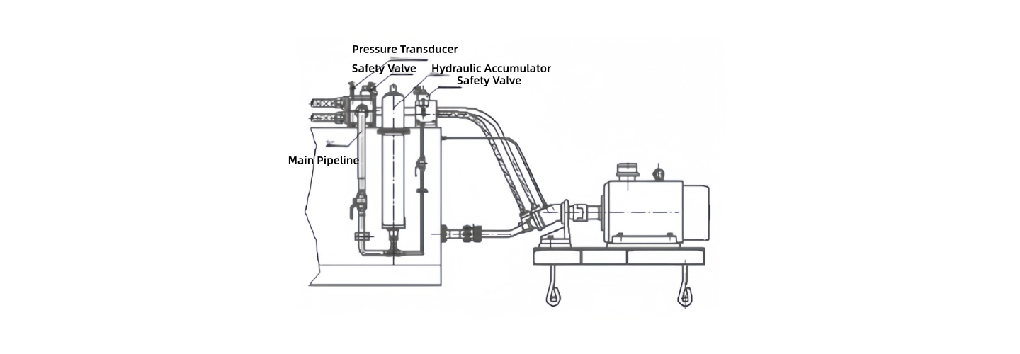
Schematic Diagram of a Pipeline Buffer Accumulator Installed in the Transmission Direction
Schematic Diagram of Multiple Nodes in a Pipeline with Safety Valves Installed
The gas bottle group is connected to the upper ports of the accumulators, ensuring rapid fluid replenishment during striking and swift return stroke.
2.3.4 Piping
Hydraulic and pneumatic pipelines are laid as parallel as possible without interference. Flanges, fittings, elbows, and pipe clamps are reasonably added. Pipe supports are securely fixed, facilitating disassembly/assembly, reducing energy loss, and minimizing pipe vibration.
During forging hammer operation, fluid flow within the system frequently changes direction at high speed and pressure, inevitably generating high-energy hydraulic shock in the pipes. To ensure reliable connections and good, leak-free sealing when hydraulic shock vibration in the system is significant, pipeline buffer accumulators are installed in the direction of shock transmission, and anti-vibration pipe clamps are reasonably added to reduce vibration and eliminate leakage. Safety valves are installed at multiple pipeline nodes. Simultaneously, the pressure rating of hydraulic pipes is increased by one grade to improve the equipment's overall multi-layer safety.
During pipeline installation, acid cleaning, passivation, rust prevention, and overall color coding are performed according to Chinese national standards. Flow direction indicators and valve open/close markings are painted for easy identification and judgment.
2.3.5 Lubrication System
The equipment is equipped with a shock-resistant automatic lubrication system, primarily for lubricating various guide rail surfaces, ensuring an oil film coverage of ≥80% on lubricated surfaces during operation. The lubrication station is fixed to the pipe support via spring suspension, ensuring normal oil supply during vibration.
Before starting the machine, check the lubrication condition of the guide rails. If necessary, lubricate the guide rails manually with a grease gun. Operating the equipment without lubrication is prohibited.
2.4 Electrical Section
The electrical system uses PLC control, enabling one-button start and stop operation. It features a full Chinese menu display, touch screen input, and can display pressure, temperature, liquid level, faults, and alarms.
The electrical control includes automatic unloading functions (including start-up unloading), pressure loss protection, and overpressure protection. When a component in the hydraulic system fails due to fatigue causing leakage or when a fault causes overpressure, a pressure sensor sends a signal to control the main pump to unload and stop, providing pressure loss and overpressure protection.
The electrical system has temperature alarm and automatic cooling functions. When the system oil temperature exceeds the set value, the PLC controls the electric chiller to operate, ensuring normal system function.
The electrical section has motor protection, display, and alarm functions, automatically monitoring the electrical system for overload, phase loss, leakage, and short circuit.
Motor starting employs a star-delta start, with low starting current to avoid significant impact on the power grid.
The control cabinet uses dust-proof mesh and cooling fans to ensure reliable dust prevention, heat dissipation, and sealing. Wiring separates high-power and low-power lines or uses shielded cables. All electrical lines are clearly marked with wire numbers for easy identification.
III. Technological Advancement and Rationality of the C66YA Fully Hydraulic Open-Die Forging Hammer
Single-lever control achieves various functions—slow ascent/descent of the hammer head, striking, return stroke, rapid retraction, suspension at any position, and continuous strikes at different stroke lengths and frequencies—enabling user-friendly and flexible operation.
Both the rapid feed inlet and quick discharge outlet are servo-controlled, preventing occasional malfunctions seen in hydro-pneumatic electric-hydraulic hammers, thereby enhancing operational safety and reliability.
The actuating valve combines spool valve operation with poppet valve sealing, improving controllability and sealing performance at valve ports. This reduces internal leakage and minimizes heat generation within the system.
The main control valve is a self-developed servo valve with broad applicability, suitable for 1–20-ton die-forging hammers and 1–10-ton open-die forging hammers.
Real-time monitoring of system oil consumption: when demand is high, multiple pumps operate under load simultaneously; when demand is low, individual pumps remain loaded while others are forcibly unloaded. This significantly reduces the unloading frequency of pumps and unloading valves, lessens hydraulic shocks, and extends the service life of pumps and unloading valves (proprietary technology).
The system incorporates overpressure and loss-of-pressure protection. In events such as main inlet hose rupture or oil spray from the lower seal due to hammer rod fracture, the system promptly shuts off the main oil outlet and stops the motor immediately, enhancing system safety. This patented technology uses pressure signals from the lower chamber of the hammer rod piston and employs mechanical interlocking for safety protection, eliminating reliance on electrical signals for circuit switching (proprietary technology).
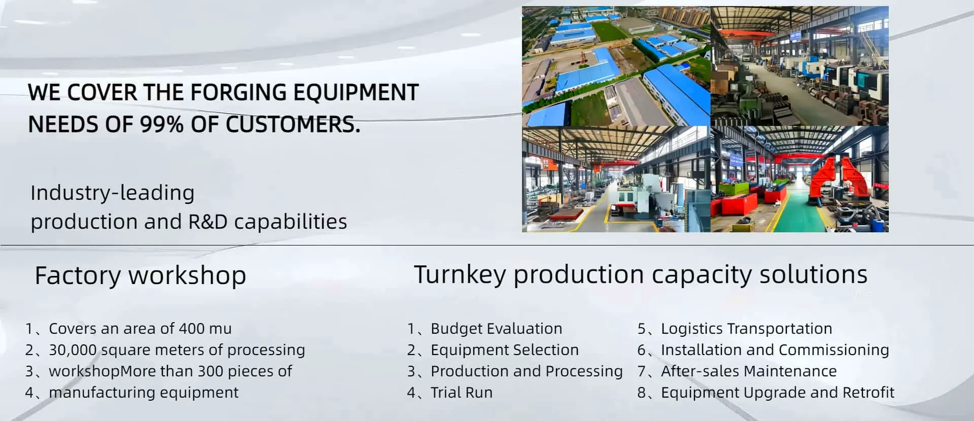
IV. Description of AYANK FORGING's Manufacturing Capability
Among the workers, inspectors, and assemblers involved in manufacturing our fully hydraulic forging hammers, 98% are skilled technicians. All have completed the company's training program on fully hydraulic electro-hydraulic hammers, giving them a comprehensive understanding of the hammer's structure, performance, and the importance of each component. Of the frontline workers, 68% are technical school graduates, 30% hold college or specialized secondary diplomas, and the remaining 10% come from other educational backgrounds. We have successfully delivered over 600 high-quality units to customers across the country.
· The machining precision of the hammer body is critical. Specifically, the symmetry of the "X"-shaped guide rails and their perpendicularity to the dovetail surfaces directly affect assembly quality. To ensure precision, our process engineers formulate detailed machining plans and inspection procedures. Critical machining operations are performed on large CNC floor-type boring mills, meeting all specified drawing requirements.
· The precision of the main control valve is vital for system control. All crucial machining for these components is completed on CNC lathes.
· The cylinder sleeves demand extremely high precision, with strict requirements for concentricity of the inner and outer diameters, cylindricity of the inner bore, and surface roughness, making them challenging to machine. Our company employs a process of machining on deep-hole boring machines followed by finishing with ultra-precision internal roller burnishing tools. This ensures both bore accuracy and surface strength. Final machining of the outer diameter is completed on grinding machines.
· Hammer head components are machined on machining centers, guaranteeing high-quality production of the hammer heads.
V. Applicable Industries
The fully hydraulic open-die electro-hydraulic hammer is suitable for various open-die forging processes such as drawing out, upsetting, punching, shearing, forge welding, twisting, and bending. It can also perform various open-die impression forging operations when using die inserts.
VI. Notable Energy Efficiency of Fully Hydraulic Electro-Hydraulic Hammers
The primary energy utilization rate for steam or air compressor-driven forging hammers is less than 2%, sometimes as low as 0.2%. In contrast, the fully hydraulic electro-hydraulic power unit can achieve a primary energy utilization rate of up to 20%. Retrofitting with a fully hydraulic power unit—by replacing the inefficient pneumatic drive system and restoring the equipment's operational accuracy—can achieve energy savings exceeding 90%. This enhances the forging capacity of the equipment while significantly reducing energy consumption and lowering production costs.
VII. Technical Features of the Fully Hydraulic Open-Die Electro-Hydraulic Hammer
The fully hydraulic power drive system prevents cross-contamination between oil and air, substantially extending the service life of the hammer rod piston seal.
The backpressure in the upper chamber during the return stroke is very low. This eliminates the "dead blow" effect during striking, increases return speed and striking frequency, and results in high production efficiency.
The X-shaped guide rail structure multiplies the service life of the hammer rod, transforming it from a traditional "wear part" into a "long-life component."
The striking valve utilizes a differential servo principle, offering high operational flexibility and easy control over both light and heavy blows.
The striking valve incorporates an ingenious spool valve and poppet valve structure, ensuring excellent system pressure retention without a rise in oil temperature.
Advantage: High cost-effectiveness. It is particularly suitable for open-die forgings that do not require extremely high striking precision, especially medium to large-sized open-die forgings.