I. Classification and Introduction of Existing Screw Presses in the Market
III. Introduction to Product Advantages
V. Value-Added Functions and Services
XI. Maintenance and Care for Electric Screw Presses
The screw press is a type of forging equipment. After decades of development, three main categories dominate the current market: friction screw presses, CNC electric screw presses, and servo direct-drive electric screw presses.
Their common characteristic is the use of the screw transmission principle, employing a screw and nut as the transmission mechanism. The screw drive converts the forward and reverse rotary motion of the flywheel into the up-and-down reciprocating motion of the slide, thereby forging and forming the workpiece. During operation, the drive system accelerates the flywheel's rotation to store energy while simultaneously driving the slide downward via the screw and nut. When the slide contacts the workpiece, the flywheel is forced to decelerate to a complete stop. The stored rotational kinetic energy is transformed into impact energy, which is delivered through the slide to strike and deform the workpiece. After the impact, the motor reverses the flywheel's direction, driving the slide upward to return to its initial position. The development of screw presses primarily involves the continuous iteration and upgrade of the drive and transmission systems, progressing towards higher efficiency and energy savings, improved safety and environmental friendliness, greater applicability, and enhanced precision.
Friction screw presses are typically driven by a motor that rotates a transmission shaft in one direction via V-belts. Two friction discs mounted on this shaft rotate with it. When the slide descent button is pressed, a directional control valve shifts, causing an operating cylinder piston to move downward. Through a lever system, this moves the main shaft rightward along its axis, pressing the left friction disc against the flywheel. Friction then drives the flywheel to rotate, converting its circular motion into the slide's linear motion via the screw mechanism. After the slide contacts the workpiece through the die, all the kinetic energy accumulated by the flywheel and slide during motion is released. The flywheel's inertial torque is converted into the forging force applied by the slide to the workpiece via the screw mechanism. Once a forging blow is completed, pressing the slide ascent button shifts the directional control valve. The operating cylinder piston moves upward, and through the lever system, the right friction disc presses against the flywheel. The flywheel rotates in reverse, returning the slide. When the slide rises to a preset position, the directional control valve shifts again. A return spring restores the friction discs to their neutral position, while a simultaneous braking action stops the slide at the set point.
Electric screw presses utilize a motor to drive the flywheel/large gear—and the screw fixed to it—in forward and reverse rotation via a pinion gear. The screw drives the slide in its up-and-down reciprocating motion. Upon receiving a start signal, the motor drives the screw and slide to accelerate downward through the pinion and flywheel/large gear. When the motor reaches the rotational speed required for the preset impact energy, it ceases acceleration. The kinetic energy stored in the flywheel/large gear performs the work to form the part. Concurrently, the motor immediately drives the large gear in reverse. After returning through a specific angle, the motor enters a braking state, causing the large gear to drive the slide back to the preset position.
Friction screw presses represent an older generation of products. At the time of their prevalence, motor technology was less advanced, necessitating the use of friction discs for energy storage. They involve more transmission stages, resulting in higher energy losses, and require more frequent maintenance at a higher cost.
Electric screw presses are upgraded products based on friction screw presses. They eliminate the friction disc transmission, incorporate a digital control system, and feature a shorter transmission chain, leading to improved energy efficiency utilization. Industry energy savings are approximately 50%-55% compared to friction presses, with reduced maintenance frequency and cost. The digital control system and closed-loop position control significantly enhance forging precision and consistency.
Direct-drive screw presses are a further upgrade from electric screw presses. They employ an AC permanent magnet synchronous servo motor to directly drive the flywheel/large gear, while other principles remain identical to electric screw presses. Compared to standard electric screw presses, the servo motor in a direct-drive model is directly connected to the screw. This results in a more compact structure, fewer transmission stages, higher efficiency, greater precision, lower noise, longer lifespan, and makes them particularly suitable for high-precision, advanced forgings.
Due to their inherent limitations, friction screw presses are minimally produced by manufacturers today, remaining mainly as legacy equipment in the market. Currently, CNC electric screw presses are predominant. The following section provides a detailed introduction to CNC electric screw presses.
Product Introduction
The CNC Electric Screw Press employs frequency conversion control technology, featuring a simple and reliable structure. It allows for the digital setting of striking energy, ensuring stable energy output. This reduces mechanical and thermal stress on the dies, thereby extending their service life. With advantages such as relatively short forging strokes, stable output energy, and high repeatability, it is suitable for processes including pre-forging, precision forging, trimming, straightening, and coining of steel, aluminum, and other alloys. It is an energy-saving, environmentally friendly forging press with excellent performance, wide applicability, and process adaptability. It is extensively used in automotive, railway, shipbuilding, coal machinery, medical devices, hardware, cutlery, aerospace, and other fields.
Functional Advantages
With its unique transmission principle, the electric screw press combines the dual characteristics of both a forging hammer and a press. For larger die forgings, it can form parts through multiple strikes and is capable of single strikes, continuous strikes, and inching. The striking force is related to the deformation of the workpiece: it is smaller with greater deformation and larger with smaller deformation (e.g., during cold striking). In these respects, it resembles a forging hammer. However, its slide speed is low (approximately 0.5-0.7 m/s, only about 1/10 that of a forging hammer), and the striking force is contained within the closed frame. This results in stable operation, significantly less vibration than a forging hammer, and eliminates the need for a massive foundation. The screw press is equipped with a slip-type safety mechanism that limits the maximum striking force to within twice the nominal pressure, protecting the equipment.
Compared to crank-driven mechanical presses, the screw press has no fixed bottom dead center, allowing for digital control of the stroke position.
Compared to die forging hammers and hot die forging presses, it offers advantages such as a wider range of process adaptability, high cost-effectiveness, simple structure, easier operation and maintenance, and lower maintenance costs.
Compared to friction screw presses and hydraulic presses, it presents outstanding advantages including lower operating noise, a shorter transmission chain, higher striking efficiency, and accurate, stable control of the striking energy.
Product Features
Energy-saving and environmentally friendly: Saves 50%-55% energy compared to friction screw presses, with low noise and vibration.
Simple structure, high transmission efficiency, low maintenance cost.
Striking energy can be precisely controlled, resulting in small forging tolerances and high forming accuracy.
Strong process adaptability, convenient stroke height adjustment, and capable of multi-station forging.
Digital control system: Simple operation, easy maintenance, with provision for intelligent control functions.
The motor uses a variable frequency drive, causing no impact on the power grid or other equipment.
Capable of program forging, automatically executing strikes according to preset striking parameters.
AYANK FORGING Electric Screw Presses also offer the following advantages:
The flywheel utilizes friction-based overload protection, ensuring safety and reliability.
The frame possesses higher rigidity and strength, with strong anti-eccentric load capacity and a long service life.
Advanced intelligent control system with a high overload coefficient and stable performance, causing no impact on the power grid or other equipment.
High precision, with high stability in control and transmission. Striking energy can be precisely controlled, yielding high forming accuracy.
Multiple frame configurations / tailor-made solutions, with various optional device systems available.
Automatic centralized lubrication system for more reliable lubrication, significantly extending the service life of key components.
Intelligent monitoring and control system capable of online data acquisition (motor temperature, slide position, slide speed, actual striking energy, etc.), enabling closed-loop control and monitoring/recording of equipment operation status.
High Control Precision
The press is equipped with an HMI (Human-Machine Interface) for the digital setting of all parameters. It utilizes a Siemens PLC controller combined with an ABB frequency inverter to control an AC variable-frequency motor, governing both the striking energy and position. A position encoder controller provides real-time feedback of the slide's position. This enables closed-loop control of the stroke with the control system, achieving precise regulation of forging energy and position. This ensures high forging accuracy and consistency.
High Allowable Load
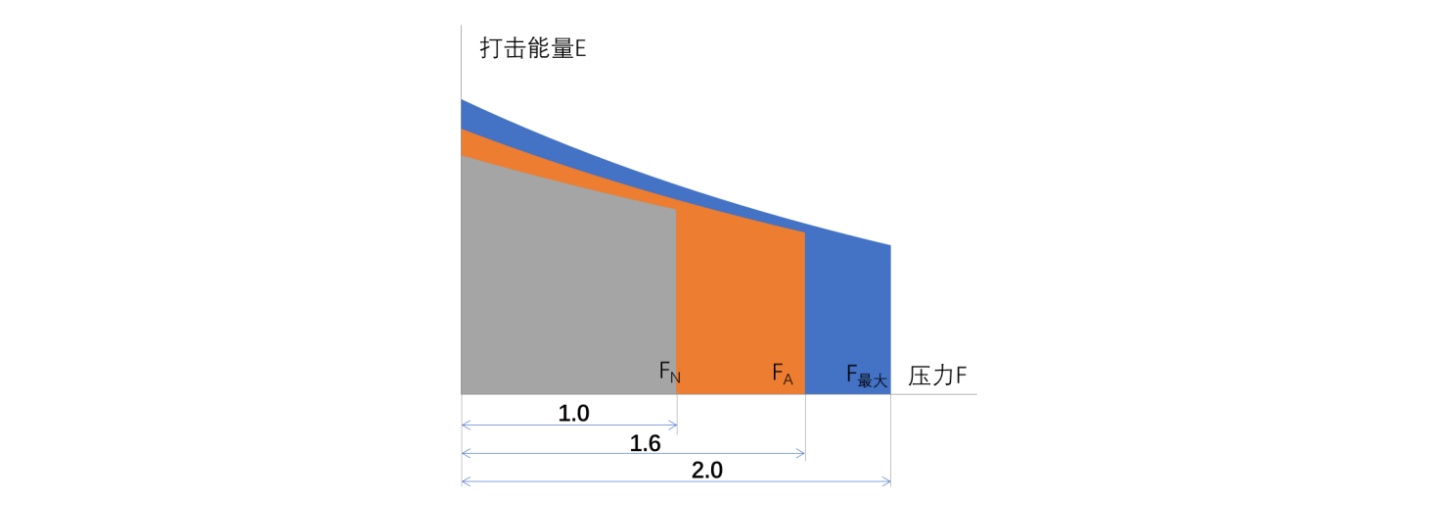
The screw presses manufactured by our company can achieve a maximum pressure (indicated in blue) of up to twice the rated pressure. The long-term allowable working pressure (indicated in red) can reach 1.6 times the rated pressure.
Energy Efficiency and High Performance
Energy Saving and Consumption Reduction:
Through an Optimized Screw-Nut Structure: Featuring a unique screw pair thread profile design, scientifically determined lead angle (ψ) and thread angle (α), higher surface strength and superior finish, and ample surface lubrication, effectively reducing frictional energy loss (Ef).
Through an Excellent Frame Design Structure: Utilizing finite element analysis to optimize stress distribution, incorporating pre-stress mechanisms to minimize deformation, and employing first-class casting and heat treatment processes to ensure frame strength, thereby reducing frame deformation energy loss (Ew).
Energy Efficiency and High Performance
Frequency-Optimized Motion Program Design: Through specialized programming and precise position/speed feedback from encoders, leveraging the PLC's rapid computational power and the frequency inverter's superior response, we have developed the equipment's unique "Short-Stroke Strike" function. This feature ensures the press can maintain a high striking frequency even at lower energy settings, saving time and improving efficiency for your operations.
High Striking Energy
The equipment's relatively large striking energy, combined with a consistent slide speed, makes it highly suitable for forging products with deep die cavities.
Strong Anti-Eccentric Load Capacity
The configuration of a long slide, long guideways, and a robust screw ensures the equipment possesses high resistance to eccentric loads. This makes it suitable for forging environments with a certain degree of off-center loading and enables multi-cavity forging for both pre-forging and precision forging operations.
Intelligent Data Control System
The Intelligent Data Control System includes: operational status control, comprehensive efficiency evaluation, equipment operation and maintenance information, maintenance cycle management, historical alarm records, and document query functions.
It Enables:
Equipment Operation Status Monitoring: Strike stroke, strike energy, real-time slide position, strike count, etc. Motor operation status: voltage, current, torque, speed, etc. Frequency inverter status, transmission temperature curves, PLC input/output monitoring, current final forging thickness, etc.
Equipment Overall Efficiency and Energy Consumption Evaluation: Time utilization rate, full production rate, quality index, power consumption analysis, etc.
Equipment Maintenance and Early Warning: I/O mapping table, quick start guide, common fault guide, maintenance schedule, maintenance cycle management, electrical manual, mechanical manual, etc.
Functions:
Predictive: Forecast production changes based on periodic capacity statistics.
Decision-Supportive: Optimize equipment utilization to reduce energy waste based on consumption statistics.
Preventive: Minimize unplanned downtime caused by equipment failures.
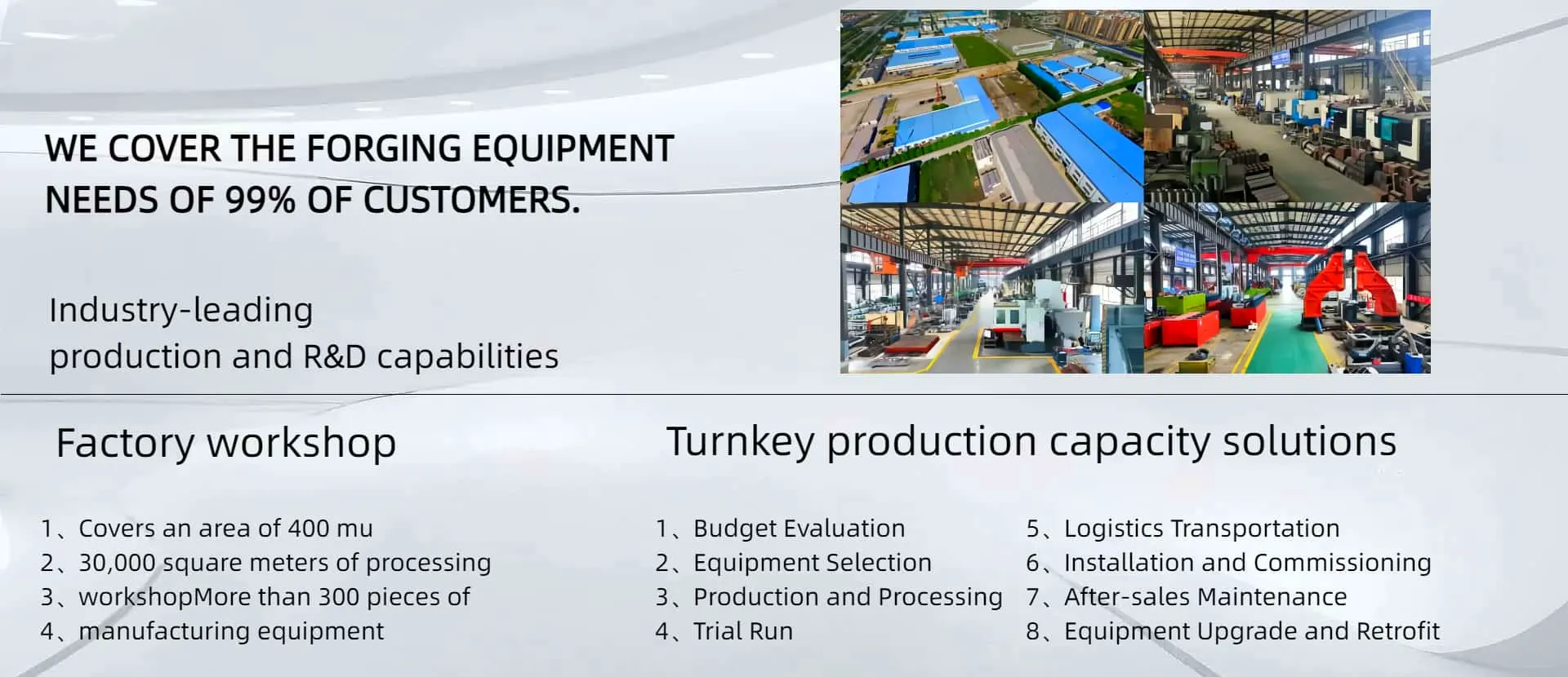
With 70 years of experience in manufacturing forging equipment and serving the forging industry, AYANK FORGING possesses a professional design and installation team as well as advanced processing and manufacturing equipment. We have full in-house design and machining capabilities for all fundamental components of screw presses, providing a reliable guarantee for product stability and dependability.
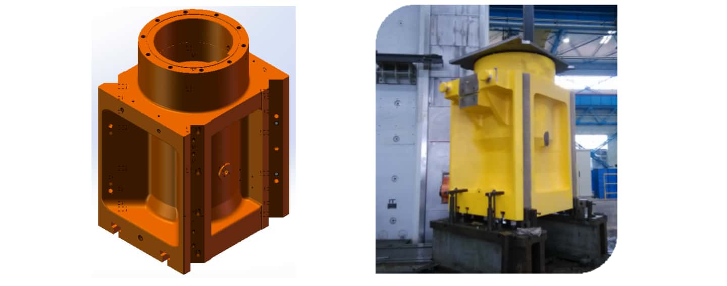
Frame Section

For presses with a capacity of 1600 tons and below, a one-piece (monoblock) frame is utilized. For presses of 2500 tons and above, a split pre-stressed frame design is employed. The frame material is ZG270-500, which undergoes normalizing treatment. The frame design is optimized through finite element analysis, ensuring a rational structure that meets both strength and rigidity requirements.
Frame Machining: The company possesses strong in-house machining capabilities and completes all frame machining independently. To guarantee machining accuracy, particularly in meeting the positional tolerance requirements of working surfaces for necessary forging geometrical precision, all relevant machining on a frame is completed in a single setup by leveraging the precise rotary functions of the machining platforms.
Frame Inspection: After machining, all machined surfaces and primary load-bearing surfaces undergo rigorous non-destructive testing (NDT) to ensure defect-free components for delivery and installation. Furthermore, to verify the accuracy of relevant geometric tolerances, laser measuring equipment is used for final precision verification of the frame.
Slide Section
The slide is made from high-quality ZG270-500 material and undergoes normalizing treatment. It incorporates X-type long-stroke guideways, providing excellent guiding accuracy and strong resistance to eccentric loads. The guideway adjustment features a wedge block structure, allowing for precise adjustment via set bolts.
Slide Machining: Machining is performed using TJK6920 CNC boring and milling machines and TK42200 CNC gantry boring and milling machines. To ensure the flatness of the guideway surfaces and the die contact surface, the machined guideways undergo manual scraping.
Slide Precision Assurance: After machining is completed, all machined surfaces and primary load-bearing surfaces undergo rigorous NDT to ensure defect-free components for delivery.
Screw and Nut Section
The main nut is manufactured from high-quality ZCuZn25Al6Fe3Mn3 via centrifugal casting, offering excellent wear resistance. The main screw is a forged component made from high-quality 35CrMoV steel. Its thread profile is optimized through design, resulting in high strength and low frictional resistance characteristics.
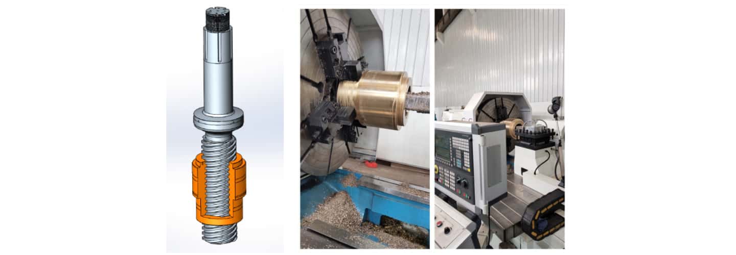
Screw and Bronze Nut Machining & Quality Assurance: Both the screw and the bronze nut are machined using CNC lathes. After the machined screw and nut are installed on the equipment and before delivery to the user, the press undergoes a 100-hour running-in test. This process allows the mating pair to complete the wear-in process and reach optimal working condition, ensuring the equipment delivered to the customer is stable, smooth, and reliable.
Electrical Control
The electrical control system primarily consists of an ABB frequency conversion control cabinet, a Siemens PLC, and an HMI (Human-Machine Interface) operator panel.
The Main Parameter Interface displays the real-time operational status of the equipment, as well as the setting and output status of the striking energy.
The Parameter Setting Interface allows for the configuration of relevant parameters such as striking energy, stroke, ejection, and lubrication.
The Recipe Storage Interface enables the programming and saving of parameter sets for specific products into a dedicated product library, facilitating direct recall in subsequent production.
The Fault Alarm Interface displays system alarm information and, based on the information, directly suggests relevant troubleshooting solutions.
Motor Section

The motor is a specially designed AC asynchronous motor featuring a 180° symmetrical design. This configuration ensures even force distribution on the flywheel, preventing uneven wear in the drive components. The pinion gear is manufactured from polymer material, offering the advantages of high strength and low inertia. The connection between the pinion gear and the motor shaft is a sliding friction type, providing effective protection for the motor during striking force overload conditions.
Braking Section
The braking system also employs a 180° symmetrical design and is installed above the flywheel. Its primary functions are to stop the flywheel and slide when required and to prevent the slide from descending under its own gravity.
Centralized Lubrication Section

The equipment's lubrication is supplied by a centralized lubrication station.
The main screw pair and the guideways are lubricated by an automatic centralized electric grease lubrication pump.
The rolling bearings, upper guide bushings, and thrust bearing assembly are lubricated by an automatic centralized oil lubrication station.
Automation Control Interface
The primary communication methods for the Siemens S7-200 SMART PLC are:
Based on the CPU's own communication ports: PPI, MPI, Freeport, USS, MODBUS, Ethernet (TCP/IP).
Based on expansion boards: Freeport, USS, MODBUS.
Leveraging these diverse communication options, suitable protocols can be selected and implemented according to the different requirements of automated production lines.
Visualized Production and Energy Consumption Analysis Interface
Through communication with the upper-level computer (Industrial PC) and utilizing relevant PLC modules, the system can perform collection, display, statistical analysis, and reporting of actual equipment operational data:
Monitor active and reactive power via current/voltage monitoring for energy consumption statistical analysis.
Log strike data to calculate actual production output, equipment utilization rate, and production efficiency.
Remote Monitoring and Diagnostics Interface (Optional)
By installing a remote control and monitoring module and utilizing network transmission with S-Line encryption, the following functions can be achieved: remote fault diagnosis, operational monitoring, and performance statistics of the equipment.
Remotely diagnose and resolve equipment faults, reducing downtime.
Perform remote system upgrades for the equipment via the network.
Monitor the actual operating status of the equipment from mobile or computer terminals.
Ejection Systems (Optional)

Lower Ejection: Utilizes hydraulic ejection with adjustable stroke and force.
Upper Ejection: Utilizes pneumatic ejection with adjustable stroke and force.
Sealing components are from internationally renowned brands, providing reliable dustproof and high-temperature resistance performance.
Improved Production Efficiency
Compared to traditional hydraulic presses: The electric screw press utilizes a variable frequency motor drive, resulting in fast system response, short cycle times, rapid operation rhythm, and high impact frequency. This makes it suitable for the production of small/medium or large batches of forgings.
Energy Saving and Reduced Consumption
High electrical energy utilization efficiency: Compared to traditional friction screw presses, gear transmission is more efficient than friction drive. The motor operates only during active use, reducing no-load rotation energy consumption.
Enhanced Forging Quality
High Precision: Enables precise control of impact force and energy, beneficial for the precision forming of complex workpieces.
Excellent Repeatability: The intelligent control system ensures consistent strike parameters for each blow, improving product uniformity, typically controlled within ±3%.
Long Equipment Life and Low Maintenance Cost
Simple Structure: The absence of clutches and complex brakes results in a lower failure rate.
Reduced Lubrication Needs: Does not require large quantities of lubricating oil, reducing equipment maintenance demands and environmental pressure.
High Level of Intelligence and Automation
Controllable and Adjustable Parameters: Parameters such as striking energy, stroke, and number of steps can be set and adjusted via the Human-Machine Interface (HMI touch screen).
Easy Integration into Automated Lines: Low impact and vibration facilitate easier implementation of automated production.
Environmental Protection and Improved Working Conditions
Lower Noise: Quieter operation compared to traditional friction screw presses and mechanical presses.
No Oil Contamination: Avoids hydraulic oil pollution in the workshop, unlike traditional hydraulic presses.
Economic Benefits: Increased efficiency, reduced energy consumption, lower maintenance costs.
Technical Benefits: High forming precision, advanced automation level, controllable parameters.
Quality Benefits: Excellent product consistency, low scrap rate.
Environmental Benefits: Low noise, no oil pollution, cleaner production.
Strategic Benefits: Drives enterprise transformation and upgrading towards "intelligent" and "green" manufacturing.
Long-term Benefits: Energy and resource conservation, labor reduction and efficiency gains, enhanced corporate image and market competitiveness.
The electric screw press is a new generation of intelligent equipment for the forging industry. It features great versatility, a simple and straightforward structure, easy adjustment and maintenance, no fixed bottom dead center for the slide (facilitating die design), and produces high-accuracy forgings. It is suitable for processes such as precision forging, coining, sizing, and straightening of steel, aluminum, and other alloys. The electric screw press can be used for both hot forging and precision forging/sizing, with broad industry applicability:
Automotive Industry: Engine components, transmission shaft parts, gear assemblies, brake disc components, etc.
Electric Motor Industry: Motor and micro-motor components, etc.
Home Appliance Industry: Appliance fittings, etc.
General Machinery Industry: Mechanical parts, automation components, etc.
Power Industry: Wind turbine blades, power line hardware (fittings), components, etc.
Aerospace Industry: Turbine blades, special fasteners and other components.
Medical Industry: Surgical forceps, etc.
Rigging & Lifting Industry: Hooks, shackles, lifting eyes, etc.
Hand Tool Industry: Pliers, ring spanners, open-end wrenches, combination wrenches, pipe wrenches, etc.
The company is certified to ISO 9001:2015 (Quality Management System), ISO 14001:2015 (Environmental Management System), and OHSAS 18001:2007 (Occupational Health and Safety Management System). A dedicated quality control team implements stringent quality management throughout the entire process: from raw material intake, processing, parts warehousing, product assembly, and testing to painting and final dispatch.
For every electric screw press, critical components such as the frame, slide, flywheel, and screw undergo non-destructive testing (NDT) at each manufacturing stage, starting from the rough casting or forging. This systematic inspection eliminates any potential quality defects.
The same CNC lathe and an identical program are used to machine the matching nut and screw, ensuring a perfect fit between the two.
Major stress points on the frame are meticulously inspected via NDT before final assembly to guarantee structural integrity.
Pre-Sales Service

Guided by the business philosophy of "Winning customers with quality, expanding markets with credibility," AYANK FORGING's professional engineers conduct comprehensive analyses based on customer requirements and suggestions. We promptly recommend suitable equipment models or design an economical and efficient process solution, proposing the highest quality product that best fits the customer's actual needs while clearly explaining the performance characteristics of the selected equipment.
During-Sales Service
We strictly adhere to all relevant contract terms, maintaining continuous communication with customers regarding production progress. Every manufacturing step is under stringent control to ensure the delivery of high-quality products that meet customer specifications, completed on schedule.
After-Sales Service
A dedicated after-sales service team provides timely, thorough, and satisfactory support. Throughout processes such as on-site unpacking and parts verification, installation and commissioning, technical training, and issue resolution, we prioritize customer needs at every step to ensure complete satisfaction. We offer free lifelong technical guidance to users.
Service Response
Our customer service hotline operates 24/7. Upon receiving quality-related feedback from users, AYANK FORGING will propose a course of action within 24 hours and dispatch personnel to the site within 72 hours to address the issue. Cause analysis and responsibility clarification are conducted after normal operation is restored.
Service Commitment
With 70 years of experience serving the forging industry, our products have undergone extensive validation, ensuring quality and durability. For any product exhibiting abnormalities within the warranty period (12 months) under normal operating conditions, AYANK FORGING is responsible for repair or replacement and provides relevant equipment maintenance knowledge.
As the saying goes, "Sharpening the axe does not delay the work of cutting wood." Similarly, in equipment operation, maintenance and care are essential components. Proper maintenance ensures the equipment remains in optimal condition, achieves good coordination between all components, preserves precision, extends service life, prevents failures, and enhances overall productivity. The correct operation and maintenance of the press directly influence the preservation of its precision and operational lifespan.
Pre-Operation Preparation
Prior to test operation, the oil lubrication station must be filled with #68 guideway oil. After one week of operation, replace it with fresh oil. Regularly check the oil tank level to ensure proper equipment lubrication.
Before test operation, fill the grease lubrication pump with #00 lithium-based grease (use #00 for spring, summer, and autumn; use #000 for winter). Start the lubrication pump to ensure the screw pair and guideways are fully lubricated before switching to automatic lubrication mode.
Two pressure grease fittings are located above the flywheel for lubricating the flywheel bronze bushings. An appropriate amount of #00 lithium-based grease should be injected quarterly.
Operational Precautions
To ensure the press maintains good working condition over the long term, the following operating procedures must be strictly observed:
(1) When performing operations involving small deformation but high deformation force with rigid impact—such as coining, straightening, forging hardware tools, cutlery, or medical devices—do not use the machine's maximum energy. The set energy must not exceed 40% of the nominal energy to prevent overload and potential equipment failure. Pay particular attention during processes like forging valves or cutlery (small-deformation forgings) and during coining and straightening operations.
(2) Regardless of whether the machine is in working or non-working status, the distance between the bottom surface of the slide and the top surface of the worktable bolster plate must not be less than 560 mm. This means the height of the die (including the die holder) must not be lower than this value.
(3) The air pressure in the pneumatic lines and the safety valves must be adjusted to the specified pressures. There should be no air leakage at any connection points.
(4) The overload safety device must be adjusted accurately, safely, and reliably. Specifically, the preload on the tie rods should be adjusted so that when the machine's striking force reaches 10,000 kN, the flywheel friction safety mechanism exhibits minimal slippage.
(5) Ensure sufficient lubricant is supplied to all lubrication points. The lubricant must be clean. Lubrication should be performed according to the requirements specified (e.g., refer to the manual or diagram, if applicable).
(6) If the guideways wear out, gib screws become loose, or during a major overhaul, adjust the guideway clearance with the goal of restoring and ensuring the press's precision.
(7) After every 10,000 operating cycles, inspect all connection points on the machine. Tighten any bolts that have become loose.
Maintenance and Care of Mechanical Components
Equipment Foundation Section
Inspect the foundation pit for contamination level; check for accumulated water or scale buildup; clean if necessary. Check the worktable plate for deformation; if deformation is found, promptly contact our after-sales service for repair. Check foundation bolts and wedge blocks for looseness; adjust preload if loose. Inspect foot pedal switches for obstruction by scale or other foreign matter affecting normal operation; clean promptly. The operating area around the ram and dies (around the die, above the slide) should always be kept clean, tidy, and free of foreign objects. Check the tightness of guideway plate screws; ensure they are not loose; if loose, tighten immediately.
Drive System
Check the axial clearance between the thrust bearing and the screw; adjust if clearance exceeds 0.7 mm. Check if the guideway clearance has increased; adjust if the combined clearance deviates from the 0.4-0.6 mm range. Inspect guideway contact surfaces for wear or scoring; contact our after-sales service department promptly if found. Check flywheel bolts for looseness; adjust preload if loose. Check the pinion gear clamping nut for looseness; adjust preload or replace disc springs if loose. Check if the backlash between the large and small gears is excessive (gear backlash should be 0.5-0.7 mm). Inspect the pinion gear for damage or carbonization; replace if damage or carbonization is present.
Braking System
Check if brake assembly screws are loose; adjust and tighten if loose. Inspect brake springs for deformation or damage; replace if found. Check brake linings for wear; the gap should be 2-3 mm; adjust or replace if beyond this range.
Hydraulic and Lubrication Systems
Inspect ejection oil pipes for damage and ensure fittings are secure. Check the lubrication system (lubrication hydraulic station): verify sufficient oil level; check for leaks at fittings or pipes. Inspect the working condition of hydraulic and lubrication pipelines for damage or leaks. Check oil levels in tanks, reservoirs, cups, and pumps; ensure they are sufficient and free from contaminants; clean promptly. Check all lubrication points, oil pipes, and fittings for oil leaks; replace seals immediately if leaks are detected.
Maintenance and Care of Electrical Systems
Electrical Control Section
Check the main power supply; verify the supply voltage is within ±10% of the rated value.
Check the emergency stop button for proper function; ensure it can stop the machine normally.
Check the frequency converter for cleanliness, ensuring it is free of dust and debris.
Check the control panel indicator lights; verify they illuminate and extinguish correctly.
Check the control cabinet buzzer; verify it sounds and stops correctly.
Check the control cabinet alarm lights; verify they illuminate, sound, stop, and extinguish correctly.
Electrical Components and Connections
Check motor connectors for looseness or deformation; adjust the preload or replace them promptly.
Check the condition of the main motor terminals; ensure they are undamaged and properly tightened.
Check the terminal screws on thermal relays; ensure all screws are securely fastened.
Inspect electrical components inside the electrical cabinet for any cracks or damage.
Check the terminal screws on all electrical components; ensure all are securely fastened.
Check the terminal screws inside the motor junction box; ensure all are securely fastened.
Pneumatic System
Check the system grounding; inspect the pneumatic system's appearance to ensure ground wire connections are intact and unbroken.
Check the working condition of pneumatic lines for any damage or leaks.
Check connection points; promptly identify and replace any worn seals.
Check the condition of air filters for issues like looseness, damage, or clogging.
Sensing System
Check the encoder drive mechanism; inspect the belt for aging or cracking and replace it promptly.
Check the pressure value display; ensure the working pressure is within the specified operating range.
Check the status of level sensors, screen blockage sensors, main air supply pressure sensor, and oil flow sensor for normal operation and the absence of alarms.
Maintenance Frequency
Strictly follow the inspection checklist to perform the corresponding daily, weekly, monthly, and quarterly checks at the specified locations and to the defined standards. Carry out the corresponding maintenance as required to ensure the equipment's overall performance and operational safety.


Receive the news that you are interested in.