II. Structure and Features of the Y13A Open-Die Forging Hydraulic Press
IV. Quality Control System of AYANK FORGING Company
V. Quality Control Measures and Plans in the Manufacturing Process of the Forging Hydraulic Press
VI. Description of Services from AYANK FORGING Company
VIII. Main Features of the Open-Die Forging Hydraulic Press
IX. Design Advantages of AYANK FORGING Free Forging Hydraulic Presses
The Y13A series open-die forging hydraulic press is a fully hydraulically controlled forging device that utilizes hydraulic pressure energy to transmit force. It operates smoothly with minimal impact, vibration, and noise. Featuring a rational overall layout and a simple structure, it is easy to adjust and maintain. The machine supports multiple functions such as forging, pressure holding, and ejection. It can deliver full power at any position and maintain the required pressure, meeting diverse process demands.
Product parameters
| Item | Unit | Y13Y-800 | Y13Y-1250 | Y13Y-1600 | Y13Y-2000 | Y13Y-2500 | Y13Y-3150 | YY13Y-4000 | Y13Y-5000 | Y13Y-6300 | Y13Y-8000 | Y13Y-10000 | Y13Y-12500 | Y13Y-16000 | ||
| Nominal pressure | MN | 8 | 12.5 | 16 | 20 | 25 | 31.5 | 40 | 50 | 63 | 80 | 100 | 125 | 160 | ||
| Clearance distance | mm | 2300 | 2600 | 2900 | 3100 | 3300 | 3800 | 4000 | 4600 | 5300 | 6000 | 6600 | 7200 | 7800 | ||
| Slide stroke | mm | 1000 | 1200 | 1400 | 1500 | 1600 | 1800 | 2000 | 2200 | 2500 | 2800 | 3200 | 3600 | 4000 | ||
| Column center distance | mm | 1900×1100 | 2200×1300 | 2600×1400 | 2800×1500 | 3200×1600 | 3600×1900 | 4400×2100 | 4600×2200 | 4700×2300 | 4800×2400 | 5100×2600 | 5500×2800 | 6000×3000 | ||
| Forging speed | Down speed | mm/s | 300 | 300 | 300 | 300 | 250 | 250 | 250 | 250 | 250 | 250 | 250 | 250 | 250 | |
| Working speed | Level 1[Nominal pressure] | mm/s(MN) | 68[8] | 68[12.5] | 180[6] | 160[8] | 172[10] | 164[12.5] | 152[16.5] | 186[16.5] | 183[21] | 183[27] | 183[33] | 180[41] | 180[53] | |
| Level 2[Nominal pressure] | mm/s(MN) | / | / | 108[10] | 105[12] | 102[15] | 104[19] | 104[23.5] | 93[33.5] | 92[42] | 92[53] | 92[67] | 90[84] | 90[107] | ||
| Level 3[Nominal pressure] | mm/s(MN) | / | / | 68[16] | 63[20] | 64[25] | 64[31.5] | 62[40] | 62[50] | 61[63] | 61[80] | 61[100] | 60[125] | 60[160] | ||
| Return speed | mm/s | 300 | 300 | 300 | 300 | 250 | 250 | 250 | 250 | 250 | 250 | 250 | 250 | 250 | ||
| Slider bottom surface | Rapid forging | Level 1 | min⁻¹ | 60-70 | 60-70 | 60-70 | 60-70 | 60-70 | 55-65 | 50-60 | 45-55 | 40-50 | 35-45 | 30-40 | 25-30 | 20-25 |
| Standard forging | Level 3 | min⁻¹ | / | / | 25-35 | 25-35 | 25-35 | 20-30 | 20-30 | 20-30 | 15-25 | 10-20 | 7-15 | 5-10 | 3-6 | |
| Travelling worktable | Distance | mm | 2700 * 1300 | 3200 * 1500 | 3500 * 1600 | 3700 * 1700 | 5000 * 2000 | 5000 * 2300 | 6000 * 2500 | 6000 * 2800 | 7000 * 3000 | 7000 * 3200 | 8000 * 3500 | 9000 * 4000 | 12000 * 4500 | |
| L& R stroke | mm | ±1000 | ±1400 | ±1600 | ±1800 | ±2000 | ±2500 | ±2500 | ±3000 | ±3000 | ±3000 | ±3250 | ±3500 | ±4000 | ||
| Dimensional accuracy | mm | ±1 | ±1 | ±1 | ±1 | ±1 | ±1 | ±1 | ±1.5 | ±1.5 | ±1.5 | ±2 | ±2 | ±3 | ||
| Total power | kW | 700 | 1050 | 1400 | 1600 | 2050 | 2500 | 3200 | 3800 | 4800 | 6200 | 7500 | 9500 | 12000 | ||
| Height above floor | mm | ≤6800 | ≤8000 | ≤8500 | ≤9000 | ≤9500 | ≤10000 | ≤11000 | ≤13000 | ≤14500 | ≤16000 | ≤17500 | ≤19000 | ≤22000 | ||
2.1 The hydraulic press control system adopts a human-machine interface for input and display, with PLC control, and incorporates multi-functional and multi-directional real-time monitoring. It enables synchronized operation between the forging hydraulic press and the manipulator (1+1 linkage). Manual adjustment, manual operation, and semi-automatic operation modes are selectable via buttons, allowing actions such as idle stroke, working stroke, return stroke, and ejection as required. The operation is convenient, safe, and efficient, with simple, lightweight controls that reduce labor intensity. Through the joystick switch, actions like descent, ascent, forging, pressure holding, ejection, and other forging processes can be easily executed.
2.2 The hydraulic system employs a two-way cartridge valve integrated control system, with a dual-stage control method for oil inlet and outlet. The main cylinder and system pipelines are unloaded via a three-stage hydraulic-electrical high-speed unloading mechanism (unloading time is only 0.3 seconds), ensuring fast, stable, and vibration-free operation.
2.3 The quick-change anvil device uses a T-slot hanging method, allowing for the replacement of different upper anvil blocks.
2.4 The replenishing system of this hydraulic press adopts a zero-pressure replenishment method with a large replenishing tank and a large filling valve built into the oil tank, offering the advantages of fast and sufficient replenishment, safety, and no external leakage.
2.5 The moving crossbeam guide and cylinder guide of this forging hydraulic press have extended lengths. The piston and slide block are connected via a spherical joint, providing strong resistance to eccentric loads and protecting the machine.
2.6 This hydraulic press utilizes dual control of position and pressure.
2.7 All control valve blocks are mounted on the oil tank, with a low maintenance position, ensuring convenient and safe maintenance.
2.8 The connections between the main piston and the moving crossbeam, as well as between the return piston and the lifting beam, are both spherical joints, effectively resolving issues of load eccentricity.
2.9 Equipped with oil temperature, liquid level, cooling detection alarms, and hydraulic system pressure detection devices, the machine undergoes comprehensive monitoring and protection.
2.10 All components of this equipment feature high safety factors, high strength, and long service life.
This forging hydraulic press is primarily composed of the main body section, hydraulic system, electrical system, lubrication system, and foundation.
The main body serves as the execution component of the entire forging equipment. It adopts a three-beam, four-column structural configuration. The upper beam, lower beam, and four columns form a rigid, enclosed frame designed to withstand the full working load of the hydraulic press. The main body section mainly consists of the main working cylinder, return cylinder, columns, upper beam, lower beam, moving crossbeam, protective sleeve, lock nuts, and filling oil tank. (Refer to the structure diagram below.)
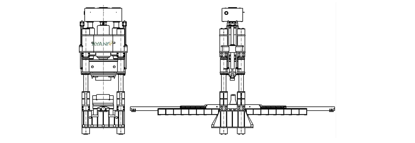
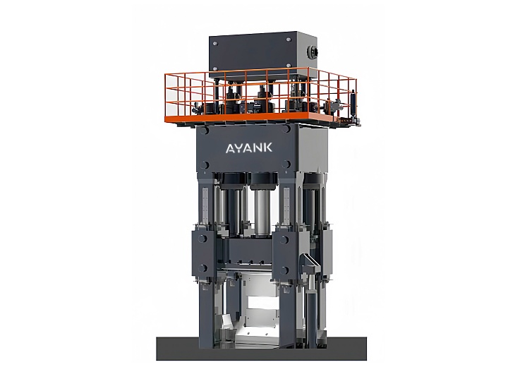
Forging hydraulic press overall structure diagram
1.1 The Three Beams
The upper beam, moving crossbeam, and lower beam are made of ZG35 (cast steel grade 35) and undergo annealing treatment for stress relief. The upper and lower beams, together with the four columns, form a rigid, pre-stressed enclosed frame to bear the hydraulic press's full working load. During installation, pre-stressed locking and fastening of the columns are achieved by applying pressure pre-tightening to the four columns and adjusting the lock nuts, ensuring stability, reliability, and structural robustness of the main body section, with strong resistance to eccentric loads.
The upper beam features mounting holes for the main working cylinder and return cylinder, as well as four column holes. It is also equipped with a stroke detection and control device to facilitate automatic control of the press stroke.
The moving crossbeam is connected to the main working cylinder piston via an open-flange bolted joint, with the pressure-bearing surfaces employing hand-scraped spherical contacts. The lower plane of the moving crossbeam is machined with locating pin holes and bolt holes for mounting the upper anvil plate. Column holes are machined at the four corners, fitted with guide bushings made of material ZQAL9-10 (a type of cast aluminum bronze).
To enhance the strength and service life of each beam, the internal ribs are arranged in a dense honeycomb grid pattern. Three-dimensional modeling and finite element analysis are utilized to optimize the beam structure to the greatest extent.
1.2 Main Working Cylinder
The required pressing force for this equipment is realized by three main working cylinders and two auxiliary cylinders. It mainly consists of the cylinder body, piston, gland, guide sleeve, and sealing rings (see diagram below). The cylinder body is constructed from forged steel grade 35 using a three-segment welded structure.

The cylinder body penetrates the upper beam, with the cylinder flange thread-connected to the lower plane of the upper beam. Cylinder positioning is ensured by the fit between two annular surfaces on the cylinder's outer wall and the beam. The piston head is connected to the moving crossbeam via a spherical movable joint, effectively mitigating hazards caused by off-center forging. The moving crossbeam descends under the combined action of the piston's self-weight and hydraulic pressure.
The pistons are made of forged steel grade 35 (#35). The surface treatment involves welding a layer of 3Cr13 stainless steel, which enhances the surface hardness. After machining, the surface roughness achieves Ra 0.8 or better. The high surface finish and hardness of the pistons extend the service life of both the pistons and the bronze bushings, improve cylinder sealing, and prolong the lifespan of the sealing rings. The sealing rings are V-rings made of fabric-reinforced rubber, offering good wear resistance. Their favorable elasticity also facilitates installation and replacement.
Main Working Cylinder Guide Sleeve
The guide sleeve for the main working cylinder is made of ZQAL9-10 (cast aluminum bronze), providing strong abrasion resistance and excellent guiding properties.
Piston-to-Moving Crossbeam Connection
The piston and moving crossbeam are connected via a flexible, spherically-supported joint. The lower part of the piston features a concave spherical surface, allowing for slight horizontal movement. During eccentric loading, when the moving crossbeam tilts under the eccentric moment, the spherical pair can slide relative to each other. Consequently, the piston transmits only axial pressure and frictional torque, significantly reducing side thrust. This design improves wear conditions for the piston guide sleeve and seals.
1.3 Return Cylinders
The two return cylinders are single-acting piston cylinders, symmetrically arranged on both sides of the frame. They serve as the actuators for the moving crossbeam's return stroke. The cylinder bodies are installed inside the upper beam, with the cylinder flanges thread-connected to the beam. The cylinder positioning is ensured by the fit between two annular surfaces on the cylinder's outer wall and the beam. The pistons are connected to the intermediate crossbeam (or moving crossbeam assembly) via a flexible, spherically-supported joint. When pressurized oil enters the cylinders, the thrust from the pistons acts on two tie rods, driving the intermediate crossbeam (or moving crossbeam) on its return stroke.
1.4 Lock Nuts and Columns
The four columns are made of forged steel grade 45 (#45), normalized after forging for stress relief and inspected via ultrasonic testing. The lock nuts are also made of forged steel grade 45, undergoing quenching and tempering (heat treatment). The threads are of a 45° buttress thread type.
1.5 Filling Oil Tank
The tank body is of welded construction. It is positioned atop the three working cylinders via filling valve seats. It is equipped with an air breather/filter. Internally, the filling valves are connected to the valve seats, ensuring smooth oil flow.
During the idle (fast approach) stroke: The moving crossbeam descends. Pressure oil from the control pump first opens the filling valves. Low-pressure oil from the tank is drawn in via self-priming through the filling valve seats, filling the working cylinders until the upper anvil contacts the workpiece.
During the working (forging) stroke: The filling valves close, ensuring the working cylinder forms a sealed chamber.
During the return stroke: The filling valves open. Driven by the return cylinders, the moving crossbeam ascends, and the oil from the working cylinders flows back into the filling oil tank through the filling valves.
1.6 Quick-Change Anvil Device
The connection structure to the anvil blocks adopts a T-slot connection form, meeting user requirements for quickly changing different anvil blocks.
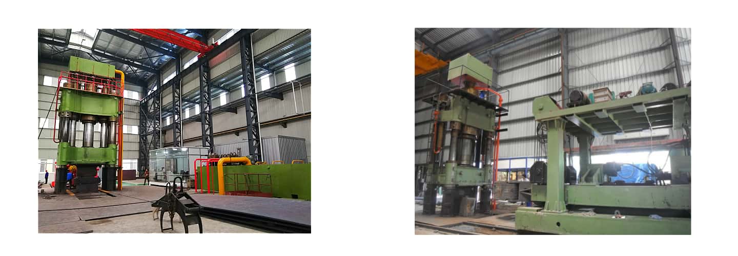
The hydraulic power unit primarily consists of the tank & piping, pump-motor sets, valve control system, replenishing system, and cooling system. Its structure features a high oil level in the tank and a flooded suction (inlet below oil level) arrangement for the pumps.
2.1 Tank & Piping
The tank is fabricated by welding channel steel grade 10 (#10) and 8mm thick steel plates. Internal baffles separate the return and suction oil zones. It is equipped with an independent hydraulic oil cooling and filtration system. The tank is a welded steel plate structure with passivation for rust prevention. The pump-motor sets are arranged on one side of the tank. The valve block control section and the cooling motor-pump set are mounted on the top surface of the tank.
Recommendation: Due to the harsh working environment of forging presses, it is recommended that users separate the pump-motor sets, main tank, and electrical control cabinet from the host machine, creating a cleaner, relatively independent space.
Given the significant hydraulic shock and vibration within the press hydraulic system, all piping connections in this machine's system use special flanges or pipe fittings with S-shaped (or face seal/O-ring) seals. Vibration-damping pipe clamps are reasonably added to reduce energy loss and prevent leaks.
2.2 Pump-Motor Sets
Main Pump-Motor Set: The main axial piston pump for the hydraulic control system is a 250MCY14-1B fixed-displacement pump (product of Shanghai High-Pressure Oil Pump Factory). The motor is a Y315L1-6-B3 motor (produced by Xinxiang Electric Motor Factory) with a power rating of 110 kW and a speed of 980 rpm. The cartridge valves are products of Jinan Casting & Forging Machinery Research Institute. The hydraulic solenoid valves are high-quality products from Beijing Huade.
Control Pump-Motor Set: This set consists of a 63YCY14-1B axial piston pump and a Y132S-4-B35 motor. The axial piston pump has a rated output pressure of 31.5 MPa and a displacement of 63 ml/rev. A pressure unloading valve block controls system pressure buildup and pump unloading. The control pump-motor set is vertically mounted on the tank, used for controlling the filling valves and other hydraulic components.
2.3 Valve Control System
The valve control system mainly comprises the main control inlet block, return valve block, pipeline unloading valve block, and external control valve block. This system employs both internal pilot (line) and external pilot hydraulic control methods, ensuring the machine's various motions remain controllable even during sudden pressure loss, preventing runaway conditions. The system uses a separate inlet and return circuit design, meaning the pressure and return lines are distinct. It implements a two-stage control system combining cartridge valves of two different nominal sizes.
The hydraulic system control valve blocks use two-way cartridge valves, a type of fluid power valve widely used domestically and internationally, particularly suitable for high-power, high-flow hydraulic control systems. They offer advantages such as simple structure, large flow capacity, strong contamination resistance, reliable performance, fast response, and flexible control methods. As this machine has requirements for fast forging processes, the main cylinder pressure relief circuit in this hydraulic control system adopts a three-stage pressure relief control circuit to enhance the main cylinder's rapid pressure relief capability and reduce relief shock and noise.
2.4 Replenishing (Filling) System
The machine's filling circuit uses normally closed filling valves. Their primary function is to supply and discharge oil for the main cylinder. When the slide moves down rapidly, a vacuum forms in the main cylinder's upper chamber, which opens the filling valve by suction. A large volume of oil from the filling tank fills the cylinder to compensate for the oil deficiency. When the slide stops, the filling valve closes. During the return stroke, pilot pressure oil opens the filling valve core, allowing oil to discharge back into the filling tank.
2.5 Cooling System
The cooling system is water-cooled, consisting of a gear pump and a plate-type cooler. The cooling oil pump set and plate-type heat exchanger are mounted on the tank.
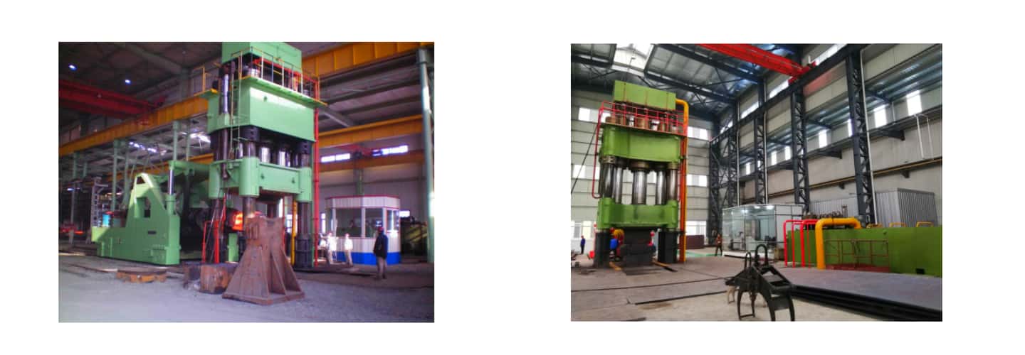
The machine's power supply is three-phase, four-wire, with a three-phase AC voltage of 380V, 50Hz. The control circuit uses DC 24V. A dedicated electrical control cabinet and a main operation console are provided. Power transmission components such as the main power switch, circuit breakers, AC contactors, control transformer, and earth leakage protection are installed inside the electrical cabinet. The cabinet is equipped with an interior light and ventilation facilities.
The main control system uses a PLC (Programmable Logic Controller) for electrical control (Omron products are selected). The main operation console is equipped with various pushbuttons and control levers. The machine's operating system offers two modes: manual and semi-automatic. The main operation console is placed on the workshop floor beside the hydraulic press for convenient operation and observation.
The primary lubrication points on this machine are between the underside of the moving worktable (or slide) and the top of the moving guideway plates. Lubrication for these points is provided by a centralized automatic lubrication system (electric lubricating pump). Lubrication between the beam guide sleeves and the columns uses grease lubrication, applied via a manual grease pump. The lubricant medium is Lithium Grease, grades 0#-1# or 0#-2#. The machine must be lubricated before each use. Operating the machine without lubrication is strictly prohibited.
The motor-pump sets are monitored via the PLC, which implements functions such as phase failure protection, short-circuit protection, over-voltage protection, and over-current protection for the motors. In the event of phase loss, short circuit, over-voltage, over-current, or overload, the PLC controls the motor to stop operation.
When hydraulic oil leakage occurs due to fatigue failure of a component in the hydraulic system, a pressure relay sends a signal. The PLC then controls the main pump to unload and shuts it down, providing pressure loss protection.
The hydraulic system is equipped with a bimetallic thermometer device. When the oil temperature exceeds the set limit, it sends a signal. The PLC then activates the cooling pump to protect the system's normal operation.
When a filter becomes clogged due to oil contamination, the monitoring device sends a signal. The PLC controls the motor-pump to stop, and the fault indicator on the pushbutton station illuminates. Operation can only resume after the filter element is cleaned.
A liquid level control relay is installed on the hydraulic power unit tank. If the oil level drops due to system leakage, the PLC control system shuts down the machine to prevent oil spillage.
The electrical control cabinet is fitted with voltage and current meters/gauges for the automatic monitoring and recording of system voltage and current.
The design and manufacturing of the hydraulic press comply with the following Chinese National Standards:
JB3818-84 "Hydraulic Press Technical Conditions"
JB3915-85 "Hydraulic Press Safety Technical Conditions"
ZBJ62025-89 "Technical Conditions for Welding of Metalforming Machinery"
GB/T5226.1-1996 "Electrical Equipment of Industrial Machines - Part 1: General Technical Conditions"
Our company obtained the ISO9001:2000 Quality Management System Certification issued by the China Quality Certification Centre (CQC) on December 31, 2001. The certificate number is 4100/200110088.
The primary documents of the Quality Management System are the "Quality Manual" and "Procedure Documents". The Procedure Documents consist of 19 files, including the Document Control Procedure, Quality Record Control Procedure, Management Review Control Procedure, and Personnel Training, Assessment, and Appointment Control Procedure, among others.
Quality Policy:
Quality First, Customer Foremost
Premium Service, Technological Innovation
Prevention Focused, Continuous Improvement
Quality Objectives:
First-time Inspection Pass Rate for Products (Complete Machine): 95%
Final Inspection Pass Rate for Products (Complete Machine) upon Delivery: 100%
Customer Feedback Information Processing Rate: 100%
The machining and assembly of critical press components are distributed across four workshops. To ensure product quality, we have established 20 Quality Control Points across these workshops. Furthermore, Work Instructions are compiled for each critical component. The tolerance requirements for each process are tightened by one-third compared to the drawings. The machining and assembly of parts strictly adhere to the Work Instructions, ensuring 100% conformity for all requirements of critical components.
For critical components, we have established individual Quality Record Cards according to the standard AD/AGC-4.0-02-2001.8. These records are ultimately consolidated into the Complete Machine File, facilitating traceability and inquiries.
Major components of the hydraulic press also have Quality Record Cards. For each major component, the conformity rate for all requirements must reach at least 97%.
It is precisely through the implementation of the aforementioned measures that we have ensured the following qualification rates:
First-time Inspection Pass Rate for Sub-assembly, Final Assembly, and Test Run: 98%
Final Inspection Pass Rate for Complete Machines upon Delivery: 100%
Our company's quality inspection system follows this workflow:
Raw Material Incoming Inspection → In-Process Inspection → Semi-finished Product Warehouse Inspection → Assembly Inspection → Final (Delivery) Inspection.
For the critical dimensions/requirements of critical components, inspection methods are implemented at each relevant process stage, ensuring 100% inspection coverage.
Key inspection and testing instruments include equipment for:
Physical and chemical testing
Metallographic analysis
Brinell and Rockwell hardness testers (Grade 2 measurement accuracy)
Surface roughness tester
Ultrasonic flaw detector
Magnetic particle flaw detector, etc.
1. The entire process from machining, assembly, to testing of the hydraulic press strictly adheres to the company's Quality Management System documents, namely the "Process Control Procedure", "Product Measurement and Monitoring Control Procedure", and "Nonconforming Product Control Procedure". Specific measures include:
Each production workshop and department, for every process, organizes production according to the drawings, process specifications, and technical standards. The quality management system combining self-inspection and specialized inspection is strictly implemented.
Operators (or teams) conduct self-inspection on parts/products upon completion of their process. Conforming and nonconforming items are separated and distinctly placed, then submitted to inspectors for verification.
Inspectors perform specialized inspection on finished parts, clearly identifying conforming and nonconforming items. Nonconforming products are promptly reported via a daily quality report and submitted to relevant departments for disposition according to the "Nonconforming Product Control Procedure". Only conforming items can proceed to the next process.
Both operators and inspectors are required to maintain proper records for self-inspection and specialized inspection as stipulated by quality management regulations.
For batch production (lots exceeding three pieces), inspectors must perform first-article inspection, in-process (patrol) inspection, and final inspection.
Parts/components that have not been inspected, or are inspected and found nonconforming without proper disposition, are strictly prohibited from proceeding to the next process or being placed into storage.
For parts requiring outsourced processing (e.g., rough castings/forgings), the Production Department is responsible for notifying the Quality Management Department to dispatch personnel for on-site inspection or incoming inspection upon delivery. Inspection records must be maintained.
Inspectors and storekeepers in the semi-finished product warehouse conduct re-inspection on items entering storage and monitor their appearance quality. Nonconforming items are not allowed into storage.
Inspectors assign and stamp identification numbers on major components and maintain proper records for archiving.
2. Product Assembly & Testing Monitoring and Control
Sub-assembly Testing and Inspection
After sub-assembly is completed, the product proceeds to the next stage for testing according to process specifications and technical requirements.
After passing self-inspection, the product is submitted to the inspector for acceptance inspection.
For products passing acceptance, the inspector must sign the test record and the process route card before the product can proceed to the painting process.
Test operators and inspectors must maintain detailed records of the testing process and performance tests according to inspection regulations.
Products failing performance tests are reworked and readjusted by the test operator. If necessary, the Technical Department and Quality Management Department assist in resolving the issues. Reworked products must undergo re-testing and re-acceptance.
Products failing performance tests cannot proceed to the painting process. Inspectors are responsible for enforcing this supervision.
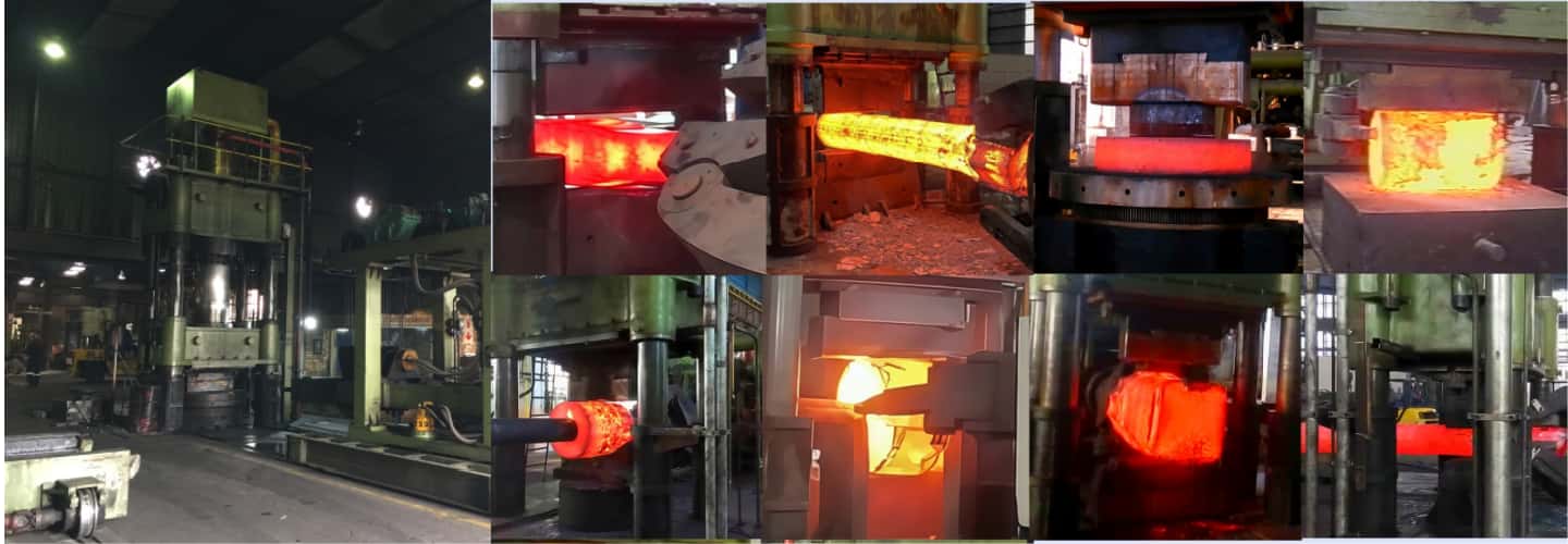
Our project engineers can arrange online video conferences to provide an overview of forging hydraulic presses internationally and specifically those manufactured by our company.
Conduct technical exchanges and detailed disclosures with your company's relevant personnel.
Submit the general layout plan within one week after the contract takes effect.
Submit various foundation drawings within two weeks after the contract takes effect.
Utilize CAD design, maintain timely communication with the user for solution optimization and design refinement.
The production process strictly follows Work Instructions for machining, inspection, and assembly, ensuring quality meets all relevant standard requirements.
Maintain timely communication with the user, keeping them informed about key technologies and production progress.
Through training provided by our company, ensure users gain a comprehensive understanding of the performance, structure, and features of our forging presses. Enable them to acquire the necessary knowledge and skills for equipment maintenance, troubleshooting, and fault elimination.
Conduct a pre-shipment inspection (pre-acceptance) with the user at our factory prior to shipment.
After shipment, a team led by a project engineer and consisting of professional personnel will carry out on-site installation.
Perform trial production and commissioning at the user's site before final handover.
Product quality is covered by a One-Year Warranty (covering repair, replacement, and return). Lifelong technical guidance is provided.
After-sales service is strictly executed in accordance with the "Warranty Statement" (attached below).
The after-sales service department operates 24/7, including holidays, providing service at any time.
Lifelong technical guidance is provided.
Provide detailed wear parts specifications and a spare parts list, ensuring supply with favorable pricing.
Products delivered ex-works are of high quality and reliability, with early-life failures eliminated within our factory.
If any quality issue is identified during the user's operation, we will respond within 48 hours of receiving user notification, or dispatch service personnel.
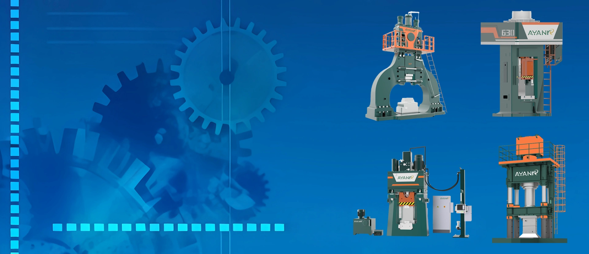
Open-die forging hydraulic presses are categorized into General-Purpose Free Forging Hydraulic Presses and Specialized Ring Rolling Blank Preparation Hydraulic Presses.
General-Purpose Free Forging Hydraulic Presses are suitable for the free forging and die forging of metallic materials. They feature functions such as rapid forging, conventional forging, and pressure holding, meeting the requirements for forging processes including upsetting, stretching (drawing-out), punching, expanding (hole enlarging), bending, and displacing (offsetting).
Ring Rolling Blank Preparation Hydraulic Presses are equipped with an automatic billet centering device and a swing-arm punch device. They can quickly perform upsetting and punching of materials. They are primarily used in conjunction with CNC radial-axial ring rolling machines.
An intelligent PLC-based operation and control system with a touchscreen human-machine interface (HMI) for interactive dialogue.
Indoor remote-control operation, resulting in low labor intensity and a favorable working environment.
A convenient and quick die-changing (upper die changing) device to enhance production efficiency.
A practical multi-point, multi-stage pressure relief system that improves equipment stability.
1 The hydraulic press control system from AYANK FORGING utilizes a human-machine interface (HMI) for input and display and PLC control, featuring multi-functional and multi-directional real-time monitoring. It enables 1+1 linkage between the press and the manipulator. It is equipped with selection buttons for manual adjustment, manual operation, and semi-automatic operation, capable of executing all necessary press actions such as idle stroke, working stroke, return stroke, and ejection. Operation is convenient, safe, highly productive, simple, and lightweight, resulting in low labor intensity. Through the joystick switch, actions like descent, ascent, forging, pressure holding, ejection, and other forging processes can be easily performed.
2 The hydraulic system employs a two-way cartridge valve integrated control system, with a two-stage control method for oil inlet and outlet. The unloading of the main cylinder and system pipelines uses a three-stage hydraulic-electrical combined high-speed unloading system (unloading time is only 0.3s), ensuring the hydraulic press operates rapidly, stably, and without vibration.
3 The quick-change anvil device uses a T-slot hanging method, allowing for the replacement of different upper anvil blocks.
4 The replenishing system of the free forging hydraulic press adopts a zero-pressure replenishment method featuring a large replenishing tank and a large filling valve built into the oil tank. This offers the advantages of rapid and sufficient replenishment, safety, and no external leakage.
5 This forging hydraulic press features a long guiding length for both the moving crossbeam and the cylinder. The connection between the piston and the slide block uses a ball head connection, providing the advantages of strong resistance to eccentric loads and machine protection.
6 This hydraulic press utilizes dual control of both position and pressure.
7 All control valve blocks are mounted on the oil tank at a low maintenance position, offering the features of convenient and safe maintenance.
8 The connections between the main piston and the moving crossbeam, as well as between the return piston and the lifting beam, all employ ball head connections, effectively resolving issues of load eccentricity.
9 The machine is equipped with oil temperature, liquid level, and cooling detection and alarm devices, along with a hydraulic system pressure detection device, providing comprehensive monitoring and protection for the machine.
10 All components of AYANK FORGING hydraulic presses feature high safety factors, high strength, and a long service life.
1. Motor Integrated Protection
The motor-pump set is monitored via the PLC, which implements phase failure protection, short-circuit protection, over-voltage protection, and over-current protection. In the event of phase loss, short circuit, over-voltage, over-current, or overload, the PLC controls the motor to stop.
2. Pressure Loss Protection
When hydraulic oil leakage occurs due to fatigue failure of a system component, a pressure relay sends a signal. The PLC then controls the main pump to unload and shuts it down, providing pressure loss protection.
3. Oil Temperature Alarm and Automatic Cooling
The hydraulic system is equipped with a bimetallic thermometer. When the oil temperature exceeds the set limit, it sends a signal, and the PLC activates the cooling pump to maintain normal system operation.
4. Filter Clogging Alarm
If a filter becomes clogged due to oil contamination, the monitoring device sends a signal. The PLC stops the motor-pump, and the fault indicator on the pushbutton station lights up. Operation can only resume after the filter element is cleaned.
5. Liquid Level Alarm
A liquid level control relay is installed on the hydraulic power unit tank. If the oil level drops due to a system leak, the PLC control system shuts down the machine to prevent oil spillage.
6. Electrical Control Cabinet
The electrical control cabinet is equipped with voltage and current meters for automatic monitoring and recording of system voltage and current.
Receive the news that you are interested in.