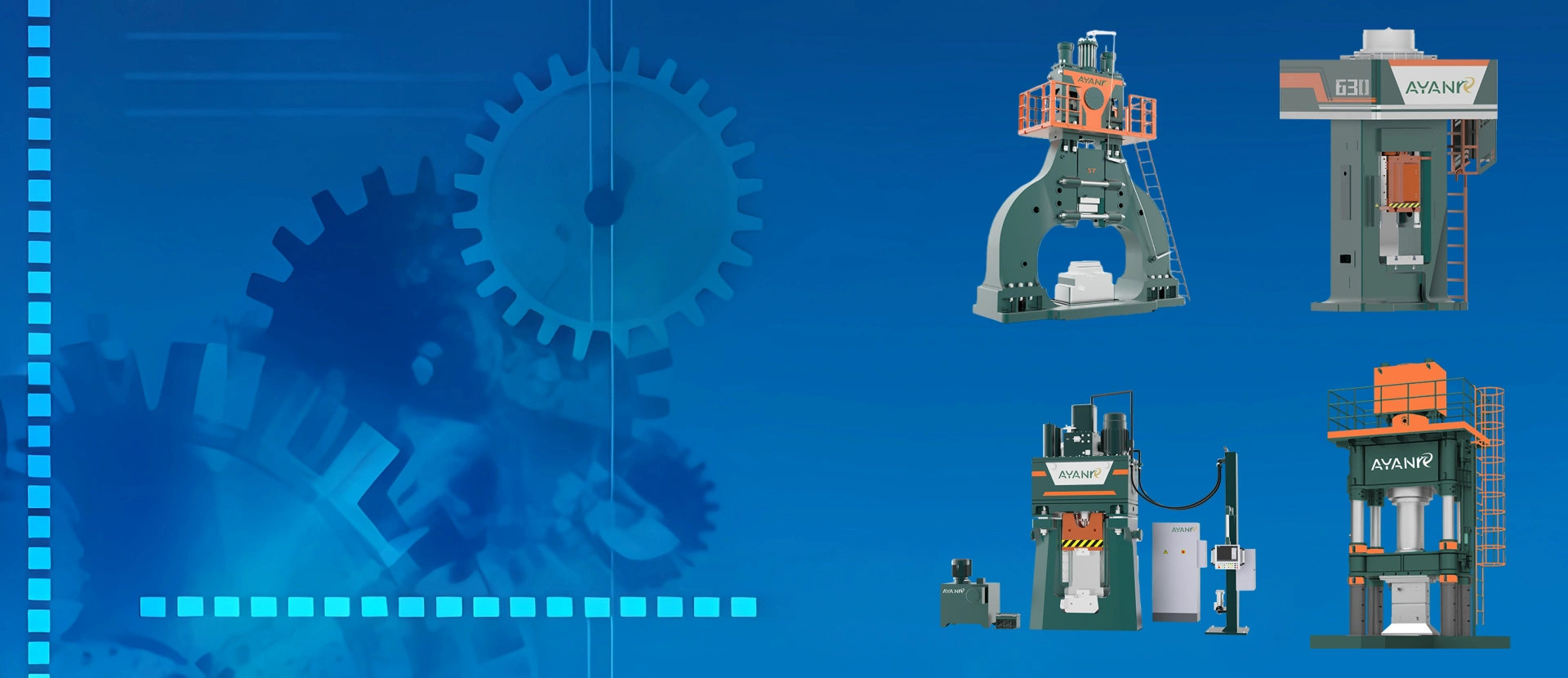
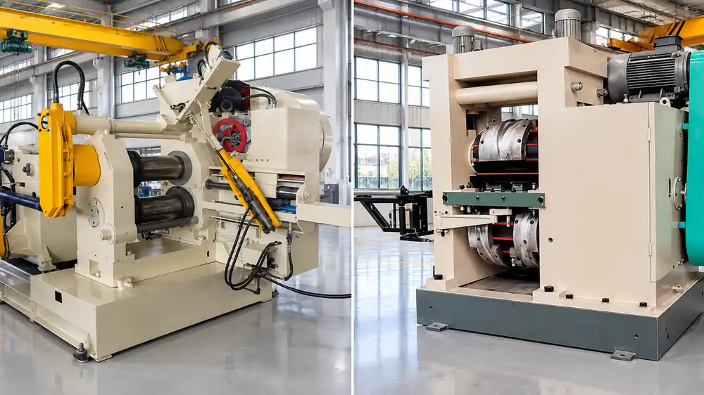
Roll forging vs cross wedge rolling is the wrong question in one respect: both sit immediately before a closed-die forging line and both reduce a heated billet's cross-section so the die has less work to do. The real choice turns on part geometry and on the size limits of the machine, not on which process is better in the abstract. This guide compares the tooling, the way the workpiece travels, the published working ranges and the cost drivers of the two, so the decision can rest on numbers rather than on brochures.
Roll forging uses grooved passes and feeds the billet lengthwise between the rolls, which makes it the choice for long shaft-type parts. Cross wedge rolling uses wedge-shaped tools that penetrate radially while the billet rotates in place, so the section is reduced and the length grows along the axis; it suits stepped, shouldered shafts. Both act as a preforming step in front of a closed-die line. If the part is long and has to be drawn out, roll forging. If the part is a stepped shaft with a workpiece diameter no larger than 165 mm, cross wedge rolling.
In roll forging, two rolls carry shaped grooves. The heated billet is fed along its axis in steps, and each pass closes a groove around one section of it. Because the billet advances between passes, a single pair of rolls can work progressively along the whole length of a long part instead of forming the entire shape at once.
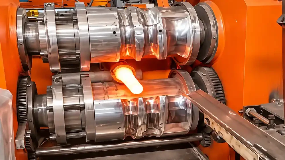
Each groove is cut to the shape the section needs after that pass. As the rolls turn, the groove squeezes the billet down to that shape, and the displaced metal moves into the length rather than out as flash. Repeating this in successive grooves produces a stepped or tapered reduction along the part. The passes can be arranged for preforming only, or to finish form sections that the die will not touch again. A transfer arm moves the billet between passes without manual handling.
The ZGD series runs six models, from ZGD370 to ZGD1250, with rolling die outside diameters from 370 mm to 1,250 mm and rolling widths from 500 mm to 1,400 mm. Maximum workpiece length rises from 570 mm on the smallest model to 2,500 mm on the ZGD1250, and maximum blank size from 50 mm square to 180 mm square, or from Φ55 to Φ200 in round bar. Roller speed falls as the model grows, from 62 rpm to 8 rpm, while main motor power climbs from 18.5 kW to 355 kW. Every model is supplied with an automatic feeding manipulator as standard. Full model data sits on the automatic roll forging machine page.
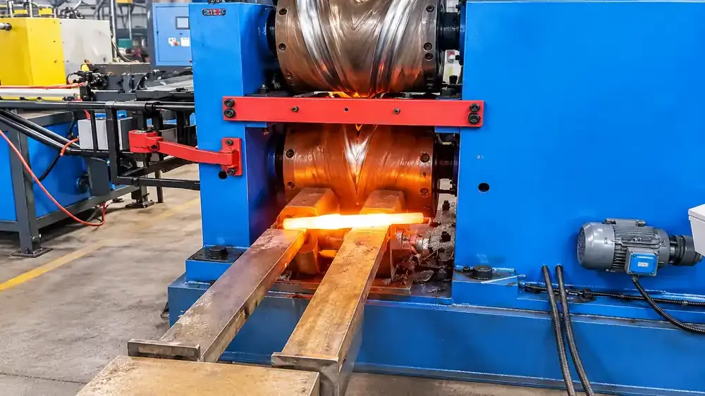
Cross wedge rolling also turns two rolls against a heated billet, but the tools are wedges rather than closed grooves. The billet rotates in place between the rolls, and the wedges enter it radially, progressively reducing the diameter while the displaced material flows along the axis. The part comes out longer than it went in, with the stepped profile already formed.
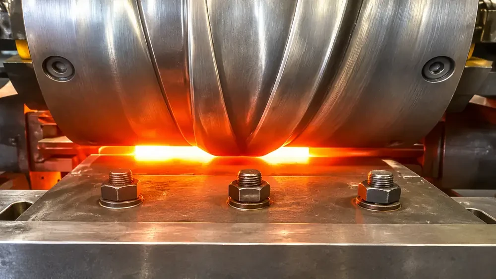
A wedge tool has a penetrating edge that widens along the roll face. As the roll turns, the edge sinks into the rotating billet and the widening flanks push metal sideways into the length. Because the billet keeps turning, the reduction is applied around the full circumference at once, which is why the process produces symmetric stepped shafts with a continuous grain flow rather than a welded or cut-up structure. No flash is produced in the rolling step. The published working range also allows cylindrical, conical and spherical profiles.
The D46 series runs six models, from D46-500 to D46-1500, with roller centre distances from 500 mm to 1,500 mm. Roller diameter runs from 400 mm to 1,200 mm and roller length from 400 mm to 1,300 mm. Maximum workpiece diameter is 35 mm on the D46-500 and 165 mm on the D46-1500, and rolling speed drops from 16 rpm to 5 rpm across the range. The roller angle is adjustable by ±3° on every model, and motor power runs from 20 kW to 315 kW. These machines are also supplied with an automatic feeding manipulator as standard. Model data is listed on the cross wedge rolling machine page.
The table below puts the published figures of both series next to each other. Ranges cover the smallest to the largest model in each series, not a single machine.
| Item | Roll Forging (ZGD) | Cross Wedge Rolling (D46) |
|---|---|---|
| Tooling | Shaped grooves, worked in successive passes | Wedge tools, radial penetration |
| Workpiece motion | Fed lengthwise, index between passes | Rotates in place, no lengthwise feed |
| Roll size | Die OD 370-1,250 mm, width 500-1,400 mm | Centre distance 500-1,500 mm, dia 400-1,200 mm, length 400-1,300 mm |
| Roll speed | 62-8 rpm | 16-5 rpm |
| Workpiece size limit | Length 570-2,500 mm; blank up to 180 mm square or Φ200 round | Diameter 35-165 mm |
| Max load capacity | 12-250 kg | Ask for the model figure |
| Main motor power | 18.5-355 kW | 20-315 kW |
| Automatic feeding manipulator | Standard | Standard |
| Machine weight | 10-120 t | Ask for the model figure |
Two rows carry no published figure for the D46 series. We would rather leave them open than estimate, so ask for the model-specific numbers when you compare offers.
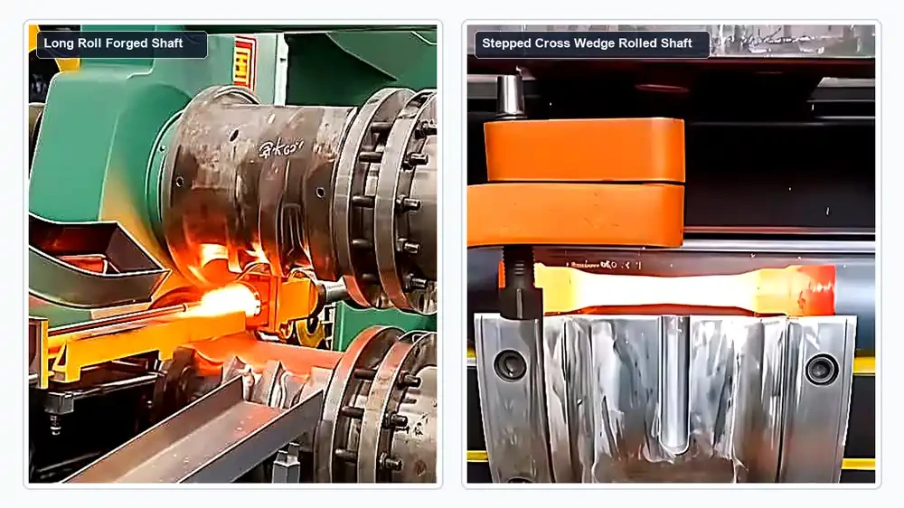
Before separating them, it is worth being clear about what they share. Both are preforming operations that sit ahead of a die forging press or hammer, and neither replaces the die. Both raise material utilization against cutting the same shape from bar, because the metal that leaves the section stays in the part instead of becoming chips. Both leave a continuous grain flow along the part rather than cutting across it. Both need the billet at forging temperature, so both depend on the heating step upstream. And both are built to run inside an automated line rather than as a stand-alone manual station. What separates them is the tooling geometry, the direction the material moves, and the size range each can accept.
These six checks settle most cases before any commercial discussion starts.
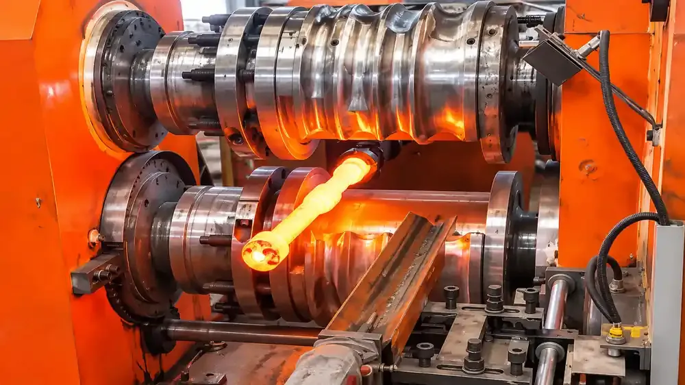
Length is a hard boundary in cross wedge rolling, because the billet stays in place and the length grows only as far as the wedge tools allow. Roll forging has a published figure instead: workpiece length up to 2,500 mm on the ZGD1250, and 570 mm on the ZGD370. If the finished part is long, start with roll forging and check the model size against your length.
The D46 series tops out at a 165 mm workpiece diameter on the D46-1500. Below that, both processes are open. Above it, cross wedge rolling is out and the decision narrows to roll forging or a different preforming method entirely.
ZGD load capacity runs from 12 kg on the two smallest models to 250 kg on the ZGD1250. If the blank is heavy, this figure, not the roll diameter, decides which model can take the job.
Distinct shoulders at defined positions suit wedge tools, which form them directly. A long taper, or a section that has to be drawn out gradually along the part, suits grooved passes, which work in stages along the axis. Parts that combine both usually get split between the two, or are rolled to an intermediate shape and finished in the die.
The ZGD series is published as combinable with CNC forging hammers, pneumatic forging hammers and screw presses, with the manipulator and automatic devices completing the line. Ask for the equivalent line configuration for the D46 series against your own press or hammer, since line integration is decided per project rather than from a catalogue. If the preforming machine is being bought to feed an existing line, describe that line before comparing models across the two series. The wider range of rolling and roll forging machines is listed separately if you want to see where these two sit among the other options.
Dedicated tooling pays for itself on a stable, high-volume part and becomes a burden in a plant that changes product often. Ask how much setup is needed when the billet size or the part geometry changes, and how many part numbers the proposed tooling set covers. A machine that is slightly slower but changes over in minutes can outproduce a faster one across a mixed order book. Give the annual quantity per part number and the expected number of changes per month, because those two figures move the tooling economics more than the machine rating does.
The part families each process is built for are different enough that the answer is usually obvious once the drawing is on the table.
The ZGD series is described for long shaft-like parts, where the reduction has to run along a considerable length rather than sit at a few shoulders. If the drawing shows a part whose useful shape extends over hundreds of millimetres, with the section changing progressively rather than at discrete steps, this is the process to look at first. A roll forged shaft leaves the machine with the reduction already distributed along nearly its full length, so the die that follows only has to finish the profile.
The D46 series is described for multi-shoulder shaft forgings, with published examples covering multi-shoulder shafts for automobiles and tractors, ball pins, spanners, pliers and connecting rod blanks. These are parts where the diameter changes at defined positions, the profile is symmetric about the axis, and the finished length is modest. Cylindrical, conical and spherical profiles all fall inside the published range. A cross wedge rolled shaft of this type comes off the rolls with the steps already in place, which is the point of rolling rather than turning the shape out of bar.
Being clear about the boundary is more useful than a longer feature list. Neither process is a final forming operation. Both deliver a preform to a die forging station, and any feature the rolls cannot reach still has to be formed in the die or machined afterwards. The size limits are also firm rather than indicative: a 250 kg blank and a 2,500 mm workpiece length are the top of the ZGD range, and a 165 mm workpiece diameter is the top of the D46 range. A part outside those figures needs a different model or a different process, not a different argument. If your part is currently rolled by hand or cut from bar and you are weighing whether a rolling step pays for itself, the roll forging as a pre-forging step page covers that case separately.
Machine price follows four things, and only the first is fully under the buyer's control.
A machine price is one line in a longer account. The comparison that matters adds tooling development, setup and changeover, material yield, cycle time, operator attention, maintenance and whatever equipment sits downstream. A cheaper machine that wastes more material or needs longer changeovers can cost more per good part over a few years than a dearer one that does not. Ask each supplier for the assumptions behind their output figure, then compare cost per saleable part across the whole route rather than the price printed on the quotation.
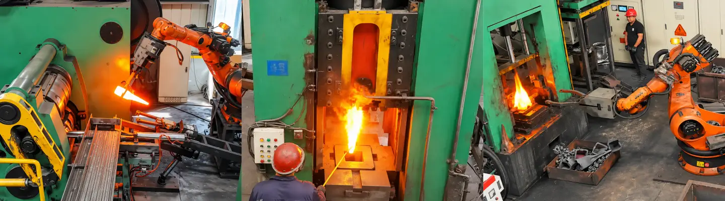
We quote against a part, not against a model number, because two buyers asking for the same ZGD model with different workpieces are not buying the same machine.
Six items are enough for a useful first answer rather than a generic price list. A complete brief also makes two quotations comparable, because every supplier is then answering the same question.
| What to send | What to include | Why it changes the answer |
|---|---|---|
| Part drawing | Overall length, section diameters, section lengths, tolerances on the rolled portion | Sets the forming geometry; a model number on its own cannot be checked against anything |
| Material and billet | Steel grade, billet size and weight, heating method | Drives the pass or wedge design, and decides whether the blank fits inside the load capacity |
| Output target | Pieces per hour, annual quantity, shift pattern | Decides the model size and how much of the handling should be automated |
| Product mix | Number of part numbers, batch size, acceptable changeover time | Decides whether dedicated tooling is justified or flexible tooling is the better buy |
| Downstream process | The hammer or press that follows, plus trimming and heat treatment | Decides the preform shape and how the two machines are connected |
| Site constraints | Floor space, crane capacity, power supply, foundation limits | Can rule out a model that is otherwise the right size |
With those, the reply can name a model and explain why, instead of sending a catalogue and asking you to work it out.
No. Both reduce a billet's section between rotating tools, but roll forging uses closed grooves and feeds the billet lengthwise, while cross wedge rolling uses wedge tools that penetrate radially while the billet turns in place.
Cross wedge rolling forms a stepped shaft in a single rolling cycle without a lengthwise feed, so it produces fewer handling steps for that part family. Roll forging needs successive passes along the length. Compare the two against your own output target rather than in general.
Yes in principle, since both are preforming steps ahead of a die forging unit, and both are supplied with an automatic feeding manipulator. Whether the combination makes sense depends on the part family and the line layout, so it is decided per project.
One is supplied as standard on every ZGD model, with a longitudinal stroke of up to 758 mm and a lateral stroke of 436 mm to 1,420 mm depending on the model. The D46 series is also supplied with an automatic feeding manipulator as standard.
Both keep the metal that leaves the section inside the part instead of turning it into chips, and cross wedge rolling produces no flash in the rolling step. The actual figure depends on the part, the pass design and the die that follows, so it is calculated per drawing rather than quoted as a general percentage.
For the rolled portion, yes. Both produce a near-shape preform that removes most of the roughing cut. Features the rolls cannot reach still need the die or a finishing operation, so the saving is in the bulk removal, not in the finished tolerances.
The six items listed above: the part drawing with tolerances, the material grade and billet size, the target output per hour, the product mix and batch sizes, the downstream forging unit, and any site constraints. With those we can name a model and explain the reasoning instead of sending a catalogue.
Send your forging drawing or part details — we will recommend the machine that fits and quote it.
Receive the news that you are interested in.