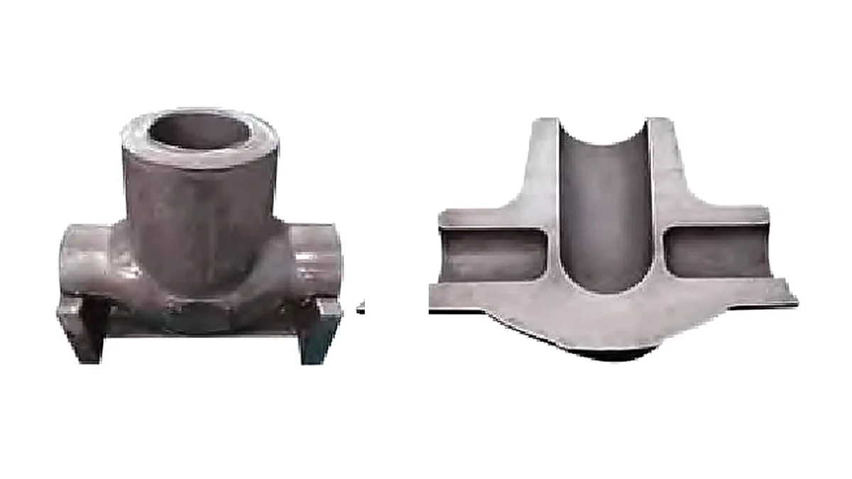
A three-way valve body starts as a solid billet. In a typical valve body forging process it is forged into a block, then the bore and both side ports are cut out on a machining centre. That route works, and most forging shops still use it, but it carries three costs that are easy to underestimate: the metal removed as chips, the hours spent removing it, and the fact that every cut crosses the grain flow of the forging.
This article explains how valve body forging works when the ports are formed instead of cut, what the process costs, and — just as importantly — where it stops being the right answer. If you are quoting a valve body order and the port machining is what kills the margin, the sections below are written for you.
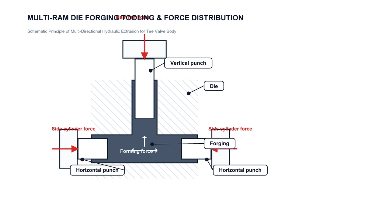
A conventional press applies force along one axis. A valve body needs force in at least two, often three: down the bore, and horizontally through each side port. A vertical press simply has no way to push metal sideways.
So the industry does the next best thing. It forges a solid blank with enough material everywhere the ports will be, then removes that material by machining. The finished part is correct, but two things happened along the way:
The second point is the one engineers tend to underestimate until a valve body fails inspection.
Multi-directional forging uses a split die that closes around the billet, plus punches that enter from several directions while the die is held shut. The cavity is closed, so the part comes out without flash and without draft angle. There is no flash to trim and no draft to machine away — the ports exist as forged geometry.
Two clarifications, because this is where marketing language usually drifts away from the workshop:
Valve body forging generally follows one of three routes, and multi-directional forging is not the answer to every valve body. The table below puts them side by side, including where the other two win.
| Route | Material use | Port machining | Tooling | Where it wins |
|---|---|---|---|---|
| Open die blank + machining | Low — large allowance everywhere | Full bore and all ports cut | Low, generic tooling | One-off and very large bodies; sizes beyond press capacity |
| Closed die forging | Medium | Ports still cut, body near-net | Moderate, single parting line | High volume, shapes without lateral ports |
| Multi-directional forging | High — ports formed to shape | None on the flow path | High, multi-part dies | Three- and four-way bodies in series production |
Route choice is driven by annual volume first, geometry second. Below a few hundred pieces a year, the tooling cost of a multi-part die rarely pays back.
Valve bodies are usually classified by how many flow paths pass through the body, and by where the flanges sit. That classification is not academic — it maps directly onto how many punches the press needs and from which direction they act.
| Type | Punch arrangement | Forming implication |
|---|---|---|
| Two-way, no side port | Main ram only | No benefit from multi-directional forming — use closed die |
| Three-way (one side port) | Main ram + one side cylinder | Single lateral punch; die must be clamped against one-sided thrust |
| Four-way (two opposed ports) | Main ram + two side cylinders | Opposed thrust balances; the classic multi-directional case |
| Multi-way with branches | Main ram + side + front/rear | Sequence is part-specific; for a T-junction the horizontal punch is normally advanced first |
| Full-flange bodies | As above, die fully enclosed | Higher clamping force; flange faces need finishing allowance |
Two hard limits apply before any of this matters:

Not sure whether your body can be formed in one piece?
Send the drawing with bore diameter, side port diameter and overall length. We will tell you which press configuration the geometry needs, and where the forming limit sits.
In a single-axis press the sequence is trivial: the ram comes down. In multi-directional forging, the order in which the punches advance decides whether the metal flows or folds.
For a T-shaped three-way body, the horizontal punch is normally advanced first, opening a path for the material. The vertical punch follows to fill the bore and the flange. Reverse that order and the vertical ram closes off the lateral escape route before the side punch has anywhere to push — the metal has no path, and the result is a lap on the bore surface that no sensible amount of machining removes cleanly.
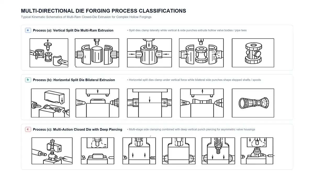
Three forming sequences. The order in which the punches advance decides whether the metal fills the branches or folds inside the cavity.
This is the reason the control system matters as much as the tonnage. A press with large cylinders and coarse sequencing will struggle on a part that a smaller machine with independent axis control handles easily. When comparing machines for this class of work, ask how many axes are independently controlled and how the sequence is programmed — not only how many cylinders are on the frame.
It also gives a practical rule for estimating: the more branches a body has, the more the die design and the punch sequence dominate the outcome, and the less the answer depends on tonnage alone.
This is the part most suppliers skip, and it is the part that decides whether a quote is realistic.
Force one — forming force. The valve body forging press must deliver enough pressure over the projected area of the part. The average die pressure depends on material, temperature and shape complexity; for closed-die work on carbon and low-alloy steels it typically falls in the 150–400 MPa range. Using a mid value of 250 MPa, a 10 MN main ram covers a projected area of about 40,000 mm², or a diameter near 225 mm.
| Projected diameter | Area | Force at 150 MPa | At 250 MPa | At 400 MPa |
|---|---|---|---|---|
| Ø150 mm | 17,671 mm² | 2.7 MN | 4.4 MN | 7.1 MN |
| Ø200 mm | 31,416 mm² | 4.7 MN | 7.9 MN | 12.6 MN |
| Ø250 mm | 49,087 mm² | 7.4 MN | 12.3 MN | 19.6 MN |
Use this as a screening table, not a quotation. The die pressure for a specific part has to be confirmed against its material and section thickness.
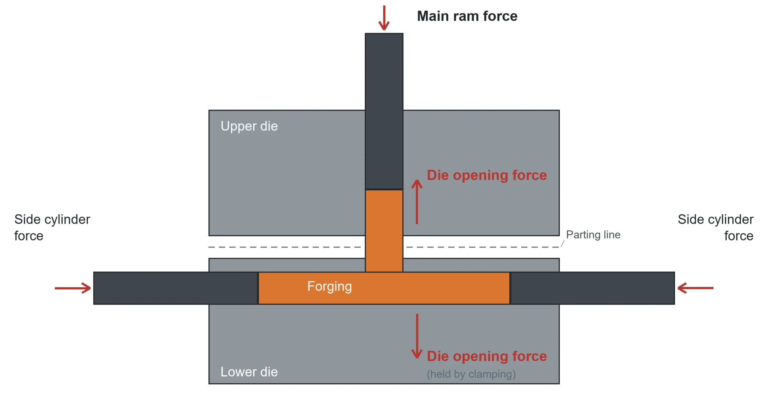
Force two — clamping force. This is the one that gets missed. A split die is pushed apart by the metal inside it, and the harder the side punches push, the harder the die halves try to separate. The clamping system has to win that argument, or the part grows flash on the parting line.
In published process data for multi-directional forging, the clamping rating frequently exceeds the forming rating. That is not redundancy — it is the consequence of a die that is loaded from the inside.
The ratio matters as much as the tonnage. On a machine configured as 1000 t main with 2 × 630 t side cylinders, the side capacity corresponds to roughly 0.63 of the main projected area — about 0.79 in diameter terms. In practice that means side ports up to about 80% of the bore diameter can be formed from the side, with little margin left at that upper bound. A Ø180 mm side port on a 6.3 MN side cylinder is already close to the limit at 250 MPa.
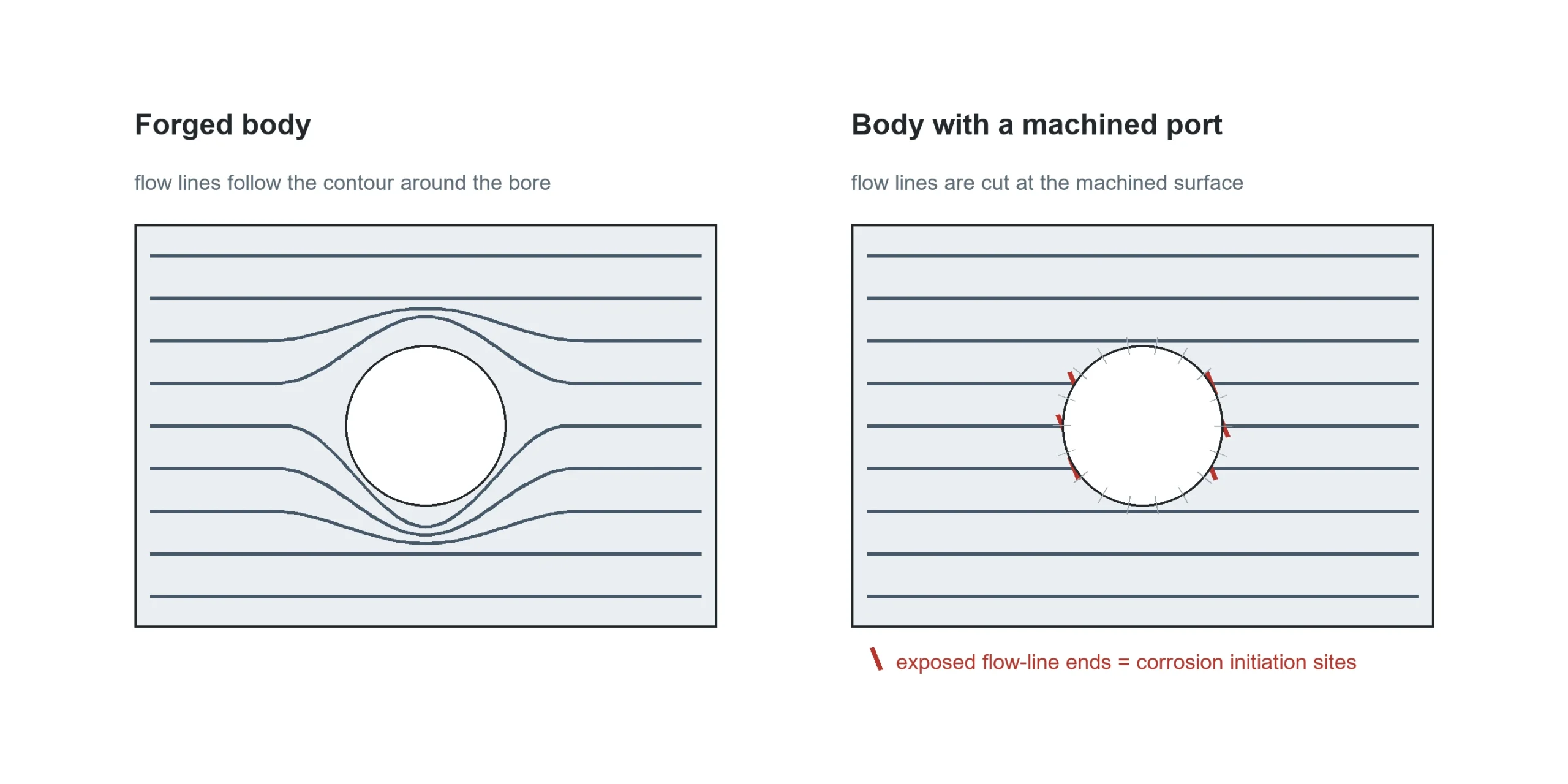
Forming the ports instead of cutting them changes the metallurgy of the finished body, not just its cost.
In a forged body, the flow lines follow the external contour and stay continuous around the bore. Nothing is cut, so no flow line ends are exposed at the wetted surface. That is the mechanism behind the improved resistance to stress-corrosion cracking that forged valve bodies are specified for in sour and high-pressure service. A machined port interrupts those lines at the most highly stressed section of the body.
The economic argument is well documented too: published work on multi-directional forging reports material and energy savings in the order of 20–35% against conventional routes, mainly from eliminating the machining allowance around the ports.
For a buyer, the practical translation is simple: the savings pay for the tooling, and the grain flow is what justifies the process to an end user who specifies forged bodies for sour service.
Three situations where a machined body is the better decision, and one where the tooling will not survive:
The flow path and the ports can be formed to near-net shape, so no machining is needed through the bore or the side ports. Flange faces and sealing surfaces are still machined, because seal tolerances are tighter than any forging process holds.
It is set by the side cylinder stroke, not by the part drawing. On a 370 mm side stroke, the formable lateral length is under 370 mm after die and spacer thickness are deducted. Longer ports need a different configuration or a two-stage process.
The final forming operation is normally a single closing stroke, but it follows a pre-gathering step that brings the material to the right distribution first. Counting the two as one operation is a common mistake in cost estimates.
Carbon and low-alloy forging steels are routine. The process also suits alloys with a narrow forging temperature window, because the multi-directional stress state raises the available plasticity. For sour service, confirm the grade and heat treatment before quoting.
A finishing allowance is normally left on surfaces that will be machined, and formed surfaces are held to normal forging tolerance. Do not expect a formed port to meet a seal tolerance — that is not what the process is for.
The drawing with bore diameter, side port diameter and overall length, plus the material grade, the pressure class and the annual quantity. Those inputs set the projected area, the side stroke requirement and whether a multi-part die pays back — which together decide the press configuration, not only its tonnage.
If the port machining is the line item that decides whether an order is profitable, the fastest way to find out is to test the geometry against the machine envelope. Send a drawing with the three dimensions that matter — bore, side port, overall length — and we will come back with which press configuration the part needs, what the side stroke allows, and where the finishing allowance has to be left. We build the press; the forging itself stays with your shop.
For the open die alternative on larger bodies, see the Y13A open die forging press. For ring-shaped parts that suit rolling rather than pressing, the radial ring rolling machine covers that route. The machine used for the process described above is the Y16A multi-directional die forging hydraulic press, and its configuration is set out there in full.
Receive the news that you are interested in.